We live on a planet with an atmosphere, a big ocean of gaseous air that keeps everything alive - and that atmosphere is constantly bouncing off of us, exerting air pressure on everything around us. But, how much air is in the atmosphere, bearing down on us?

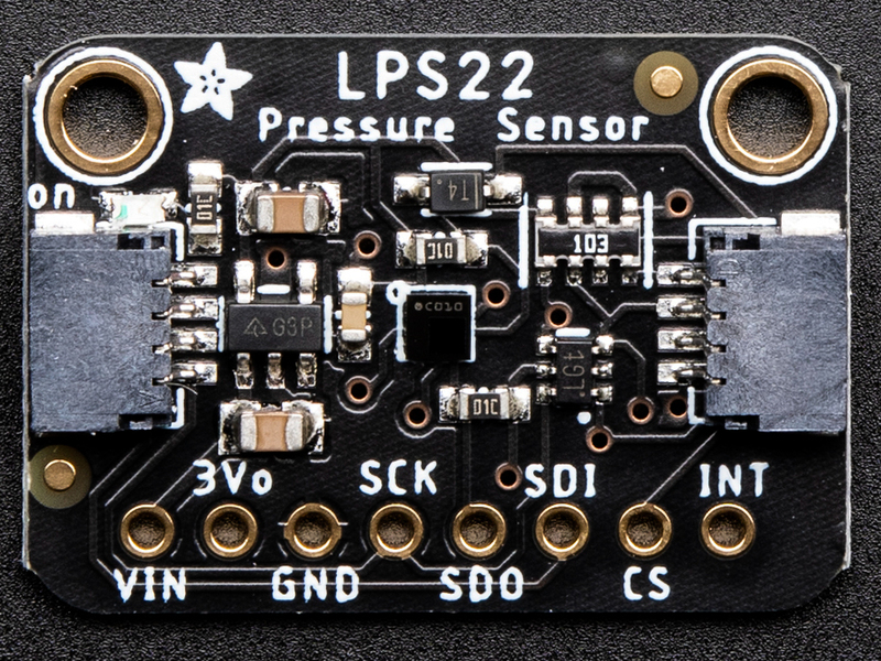
Absolute pressure sensors  like the ST LPS22HB or ST LPS25HB can quickly and easily measure this air pressure, useful when you want to know about the weather (are we in a low pressure or high pressure system?) or to determine altitude, as the air thins out the higher we get above sea level. For example, at sea level, the official pressure level is 1013.25 hPa. You can use these sensors to measure the current pressure where you are right now, to compare.

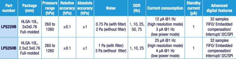
The LPS25 has a wide measurement range of 260-1260 hPa with 24-bit pressure data measurements that can be read up to  25 times a second (Hz), you can be confident that you always have an up to date and precise measurement. The LPS22 has the same measurement range but offers additional measurement rates of 50 and 75Hz. They’re pretty dang accurate too, with the ability to measure within 0.2 hPa after calibration (± 1 hPa before calibration).

This table from an overview of ST’s sensors shows how the two compare:

These days, helpful little sensors like the LPS22 and LPS25 (LPS2x’s) are often quite little and tend to come in surface mount packages that make them tricky to use with breadboards. With that in mind, we've taken both of these sensors and put  them on a breakout board with level shifting circuitry and a voltage regulator. This means that not only can you use them with a breadboard, but they can be used with a wide range of devices that have either a 3.3V logic level, like a Raspberry Pi or CircuitPython compatible Metro M4 Express, or with a 5V logic level device like a Metro 328 or Arduino Uno.

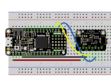
Furthermore, we've included SparkFun Qwiic compatible STEMMA QT connectors for the I2C bus so you don't even need to solder! All you need to do is plug in a compatible cable, wire it up to your device using one of our wiring diagrams and you're ready to write some code to start reporting measurements.

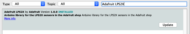
To make the coding easier, we've written libraries for Arduino and CircuitPython or Python along with accompanying example code,  so all you have to do is gather your supplies and follow our instructions and you can know just how much air is sloshing around in your vicinity.

The LPS25 and LPS22 breakouts have identical pinouts; both boards are shown for reference

Power Pins

  • Vin - this is the power pin. Since the sensor chip uses 3.3 VDC, we have included a voltage regulator on board that will take 3-5VDC and safely convert it down. To power the board, give it the same power as the logic level of your microcontroller - e.g. for a 5V micro like Arduino, use 5V, for a feather use 3.3V
  • 3Vo - this is the 3.3V output from the voltage regulator, you can grab up to 100mA from this if you like
  • GND - common ground for power and logic

I2C Logic Pins

  • SCK - I2C clock pin, connect to your microcontroller's I2C clock line. This pin is level shifted so you can use 3-5V logic, and there's a 10K pullup on this pin.
  • SDI - I2C data pin, connect to your microcontroller's I2C data line. This pin is level shifted so you can use 3-5V logic, and there's a 10K pullup on this pin.
  • STEMMA QT - These connectors allow you to connectors to dev boards with STEMMA QT connectors or to other things with various associated accessories
  • SDO - I2C Address pin. Pulling this pin low to GND will change the I2C address from 0x5D to 0x5C

SPI Logic pins:

All pins going into the breakout have level shifting circuitry to make them 3-5V logic level safe. Use whatever logic level is on Vin!

  • SCK - SPI Clock pin, its an input to the chip
  • SDO - Serial Data Out / Microcontroller In Sensor Out pin, for data sent from the LPS25 to your processor
  • SDI - Serial Data In / Microcontroller Out Sensor In pin, for data sent from your processor to the LPS25
  • CS - this is the Chip Select pin, drop it low to start an SPI transaction. Its an input to the chip

If you want to connect multiple LPS25's to one microcontroller, have them share the SDI, SDO and SCK pins. Then assign each one a unique CS pin.

Other pins

  • INT is the interrupt output pin. You can configure the interrupt to trigger for various 'reasons' such as going over or under a configured pressure threshold. Voltage level is the same as Vcc. Consult the datasheet for more information.

I2C Wiring

Use this wiring if you want to connect via I2C interface

By default, the i2c address is 0x5D.  If you add a jumper from SDO to GND the address will change to 0x5C

  •  Connect board VIN (red wire) to Arduino 5V if you are running a 5V board Arduino (Uno, etc.). If your board is 3V, connect to that instead.
  • Connect board GND (black wire) to Arduino GND
  • Connect board SCL (yellow wire) to Arduino SCL
  • Connect board SDA (blue wire) to Arduino SDA

SPI Wiring

Since this is a SPI-capable sensor, we can use hardware or 'software' SPI. To make wiring identical on all microcontrollers, we'll begin with 'software' SPI. The following pins should be used:

  • Connect Vin to the power supply, 3V or 5V is fine. Use the same voltage that the microcontroller logic is based off of
  • Connect GND to common power/data ground
  • Connect the SCK pin to Digital #13 but any pin can be used later
  • Connect the SDO pin to Digital #12 but any pin can be used later
  • Connect the SDI pin to Digital #11 but any pin can be used later
  • Connect the CS pin Digital #10 but any pin can be used later

Later on, once we get it working, we can adjust the library to use hardware SPI if you desire, or change the pins to others.

Library Installation

You can install the Adafruit LPS2X Library for Arduino using the Library Manager in the Arduino IDE.

Click the Manage Libraries ... menu item, search for Adafruit LPS2X, and select the Adafruit LPS2X library:

Then follow the same process for the Adafruit BusIO library.

Finally follow the same process for the Adafruit Unified Sensor library:

Load Example

The examples below show using an LPS25, however the LPS2X library can be used with either the LPS25 or LPS22. For the LPS22, use 'adafruit_lps22_test'

Open up File -> Examples -> Adafruit LPS2X -> adafruit_lps25_test and upload to your Arduino wired up to the sensor.

Depending on whether you are using I2C or SPI, change the pin names and comment or uncomment the following lines.

if (!lps.begin_I2C()) {
//if (!lps.begin_SPI(LPS_CS)) {
//if (!lps.begin_SPI(LPS_CS, LPS_SCK, LPS_MISO, LPS_MOSI)) {

Once you upload the code, you will see the temperature and pressure being printed when you open the Serial Monitor (Tools->Serial Monitor) at 115200 baud, similar to this:

Temperature is calculated in degrees C, you can convert this to F by using the classic F = C * 9/5 + 32 equation.

Pressure is returned in the SI units of Pascals. 100 Pascals = 1 hPa = 1 millibar. Often times barometric pressure is reported in millibar or inches-mercury. For future reference 1 pascal =0.000295333727 inches of mercury, or 1 inch Hg = 3386.39 Pascal. So if you take the pascal value of say 100734 and divide by 3386.39 you'll get 29.72 inches-Hg.

Example Code - LPS25

The following example code is part of the Adafruit LPS2X library, and illustrates how you can retrieve sensor data from the LPS25 for pressure and temperature:

// Basic demo for pressure readings from Adafruit LPS2X
#include <Wire.h>
#include <Adafruit_LPS2X.h>
#include <Adafruit_Sensor.h>

// For SPI mode, we need a CS pin
#define LPS_CS 10
// For software-SPI mode we need SCK/MOSI/MISO pins
#define LPS_SCK 13
#define LPS_MISO 12
#define LPS_MOSI 11

Adafruit_LPS25 lps;

void setup(void) {
  Serial.begin(115200);
  while (!Serial) delay(10);     // will pause Zero, Leonardo, etc until serial console opens

  Serial.println("Adafruit LPS25 test!");

  // Try to initialize!
  if (!lps.begin_I2C()) {
  //if (!lps.begin_SPI(LPS_CS)) {
  //if (!lps.begin_SPI(LPS_CS, LPS_SCK, LPS_MISO, LPS_MOSI)) {
    Serial.println("Failed to find LPS25 chip");
    while (1) { delay(10); }
  }
  Serial.println("LPS25 Found!");

//  lps.setDataRate(LPS25_RATE_12_5_HZ);
  Serial.print("Data rate set to: ");
  switch (lps.getDataRate()) {
    case LPS25_RATE_ONE_SHOT: Serial.println("One Shot"); break;
    case LPS25_RATE_1_HZ: Serial.println("1 Hz"); break;
    case LPS25_RATE_7_HZ: Serial.println("7 Hz"); break;
    case LPS25_RATE_12_5_HZ: Serial.println("12.5 Hz"); break;
    case LPS25_RATE_25_HZ: Serial.println("25 Hz"); break;

  }
}

void loop() {
  sensors_event_t temp;
  sensors_event_t pressure;
  lps.getEvent(&pressure, &temp);// get pressure
  Serial.print("Temperature: ");Serial.print(temp.temperature);Serial.println(" degrees C");
  Serial.print("Pressure: ");Serial.print(pressure.pressure);Serial.println(" hPa");
  Serial.println("");
  delay(100);
}

Example Code - LPS22

The following example code is part of the Adafruit LPS2X library, and illustrates how you can retrieve sensor data from the LPS22 for pressure and temperature:

// Basic demo for pressure readings from Adafruit LPS2X
#include <Wire.h>
#include <Adafruit_LPS2X.h>
#include <Adafruit_Sensor.h>

// For SPI mode, we need a CS pin
#define LPS_CS 10
// For software-SPI mode we need SCK/MOSI/MISO pins
#define LPS_SCK 13
#define LPS_MISO 12
#define LPS_MOSI 11

Adafruit_LPS22 lps;

void setup(void) {
  Serial.begin(115200);
  while (!Serial) delay(10);     // will pause Zero, Leonardo, etc until serial console opens

  Serial.println("Adafruit LPS22 test!");

  // Try to initialize!
  if (!lps.begin_I2C()) {
  //if (!lps.begin_SPI(LPS_CS)) {
  //if (!lps.begin_SPI(LPS_CS, LPS_SCK, LPS_MISO, LPS_MOSI)) {
    Serial.println("Failed to find LPS22 chip");
    while (1) { delay(10); }
  }
  Serial.println("LPS22 Found!");

  lps.setDataRate(LPS22_RATE_10_HZ);
  Serial.print("Data rate set to: ");
  switch (lps.getDataRate()) {
    case LPS22_RATE_ONE_SHOT: Serial.println("One Shot / Power Down"); break;
    case LPS22_RATE_1_HZ: Serial.println("1 Hz"); break;
    case LPS22_RATE_10_HZ: Serial.println("10 Hz"); break;
    case LPS22_RATE_25_HZ: Serial.println("25 Hz"); break;
    case LPS22_RATE_50_HZ: Serial.println("50 Hz"); break;
    case LPS22_RATE_75_HZ: Serial.println("75 Hz"); break;
  }
}

void loop() {
  sensors_event_t temp;
  sensors_event_t pressure;
  lps.getEvent(&pressure, &temp);// get pressure
  Serial.print("Temperature: ");Serial.print(temp.temperature);Serial.println(" degrees C");
  Serial.print("Pressure: ");Serial.print(pressure.pressure);Serial.println(" hPa");
  Serial.println("");
  delay(100);
}

It's easy to use the LPS25 sensor with CircuitPython and the Adafruit CircuitPython LPS2X library.  This library will allow you to easily write Python code that reads the pressure and temperature measurements from either the LPS22 or LPS25.

You can use this sensor with any CircuitPython microcontroller board or with a computer that has GPIO and Python thanks to Adafruit_Blinka, our CircuitPython-for-Python compatibility library.

CircuitPython Microcontroller Wiring

First wire up a LPS2X breakout to your board exactly as shown below. Here's an example of wiring a Feather M4 to the sensor with I2C:

  • Board 3V to sensor VIN (red wire)
  • Board GND to sensor GND (black wire)
  • Board SCL to sensor SCL (yellow wire)
  • Board SDA to sensor SDA (blue wire)

Python Computer Wiring

Since there's dozens of Linux computers/boards you can use, we will show wiring for Raspberry Pi. For other platforms, please visit the guide for CircuitPython on Linux to see whether your platform is supported

Here's the Raspberry Pi wired to the sensor using I2C:

  • Pi 3V to sensor VCC (red wire)
  • Pi GND to sensor GND (black wire)
  • Pi SCL to sensor SCL (yellow wire)
  • Pi SDA to sensor SDA (blue wire)

CircuitPython Installation of LPS2X Library

You'll need to install the Adafruit CircuitPython LPS2X library on your CircuitPython board.

First make sure you are running the latest version of Adafruit CircuitPython for your board.

Next you'll need to install the necessary libraries to use the hardware--carefully follow the steps to find and install these libraries from Adafruit's CircuitPython library bundle.  Our CircuitPython starter guide has a great page on how to install the library bundle.

For non-express boards like the Trinket M0 or Gemma M0, you'll need to manually install the necessary libraries from the bundle:

  • adafruit_lps2x.mpy
  • adafruit_bus_device
  • adafruit_register

Before continuing make sure your board's lib folder or root filesystem has the adafruit_lps2x.mpy, adafruit_bus_device, and adafruit_register files and folders copied over.

Next connect to the board's serial REPL so you are at the CircuitPython >>> prompt.

Python Installation of LPS2X Library

You'll need to install the Adafruit_Blinka library that provides the CircuitPython support in Python. This may also require enabling I2C on your platform and verifying you are running Python 3. Since each platform is a little different, and Linux changes often, please visit the CircuitPython on Linux guide to get your computer ready!

Once that's done, from your command line run the following command:

  • sudo pip3 install adafruit-circuitpython-lps2x

If your default Python is version 3 you may need to run 'pip' instead. Just make sure you aren't trying to use CircuitPython on Python 2.x, it isn't supported!

CircuitPython & Python Usage

These examples will show using the LPS25 however the same code can be used with either sensor by changing the LPS25 class to LPS23. See the full example code below for more information

To demonstrate the usage of the sensor we'll initialize it and read the pressure and temperature measurements from the board's Python REPL.

Run the following code to import the necessary modules and initialize the I2C connection with the sensor:

import board
import busio
import adafruit_lps2x

i2c = busio.I2C(board.SCL, board.SDA)
lps = adafruit_lps2x.LPS25(i2c)

Now you're ready to read values from the sensor using these properties:

  • pressure - The barometric pressure in hPa.
  • temperature - The temperature in degrees C.

For example to print the pressure and temperature values:

print("Pressure: %.2f hPa" % lps.pressure)
print("Temperature: %.2f C" % lps.temperature)

Example Code

# SPDX-FileCopyrightText: 2021 ladyada for Adafruit Industries
# SPDX-License-Identifier: MIT

import time
import board
import adafruit_lps2x

i2c = board.I2C()  # uses board.SCL and board.SDA
# i2c = board.STEMMA_I2C()  # For using the built-in STEMMA QT connector on a microcontroller
# uncomment and comment out the line after to use with the LPS22
# lps = adafruit_lps2x.LPS22(i2c)
lps = adafruit_lps2x.LPS25(i2c)

while True:
    print("Pressure: %.2f hPa" % lps.pressure)
    print("Temperature: %.2f C" % lps.temperature)
    time.sleep(1)

What is WipperSnapper

WipperSnapper is a firmware designed to turn any WiFi-capable board into an Internet-of-Things device without programming a single line of code. WipperSnapper connects to Adafruit IO, a web platform designed (by Adafruit!) to display, respond, and interact with your project's data.

Simply load the WipperSnapper firmware onto your board, add credentials, and plug it into power. Your board will automatically register itself with your Adafruit IO account.

From there, you can add components to your board such as buttons, switches, potentiometers, sensors, and more! Components are dynamically added to hardware, so you can immediately start interacting, logging, and streaming the data your projects produce without writing code.

If you've never used WipperSnapper, click below to read through the quick start guide before continuing.

Wiring

First, wire up an LPS22 or LPS25 (LPS2xHB) to your board exactly as follows. Here is an example of the LPS2xHB wired to an Adafruit ESP32 Feather V2 using I2C with a STEMMA QT cable (no soldering required)

  • Board 3V to sensor VIN (red wire on STEMMA QT)
  • Board GND to sensor GND (black wire on STEMMA QT)
  • Board SCL to sensor SCK (yellow wire on STEMMA QT)
  • Board SDA to sensor SDI (blue wire on STEMMA QT)

Usage

Connect your board to Adafruit IO Wippersnapper and navigate to the WipperSnapper board list.

On this page, select the WipperSnapper board you're using to be brought to the board's interface page.

If you do not see your board listed here - you need to connect your board to Adafruit IO first.

On the device page, quickly check that you're running the latest version of the WipperSnapper firmware.

The device tile on the left indicates the version number of the firmware running on the connected board.

  • If the firmware version is green with a checkmark - continue with this guide.
  • If the firmware version is red with an exclamation mark "!" - update to the latest WipperSnapper firmware on your board before continuing.

Next, make sure the sensor is plugged into your board and click the I2C Scan button.

You should see the LPS2x's default I2C address of 0x5d pop-up in the I2C scan list.

I don't see the sensor's I2C address listed!

First, double-check the connection and/or wiring between the sensor and the board.

Then, reset the board and let it re-connect to Adafruit IO WipperSnapper.

With the sensor detected in an I2C scan, you're ready to add the sensor to your board.

Click the New Component button or the + button to bring up the component picker.

Adafruit IO supports a large amount of components. To quickly find your sensor, type LPS2 into the search bar.

Double-check that the sensor you're using is either the LPS22 or LPS25. This can be found on the silkscreen on the front of your board. Then, select the sensor from the component picker.

On the component configuration page, the LPS2xHB's sensor address should be listed along with the sensor's settings.

The Send Every option is specific to each sensor's measurements. This option will tell the Feather how often it should read from the LPS2xHB sensor and send the data to Adafruit IO. Measurements can range from every 30 seconds to every 24 hours.

For this example, set the Send Every interval to every 30 seconds.

Your device interface should now show the sensor components you created. After the interval you configured elapses, WipperSnapper will automatically read values from the sensor(s) and send them to Adafruit IO.

To view the data that has been logged from the sensor, click on the graph next to the sensor name.

Here you can see the feed history and edit things about the feed such as the name, privacy, webhooks associated with the feed and more. If you want to learn more about how feeds work, check out this page.

This guide was first published on Mar 11, 2020. It was last updated on Apr 16, 2024.