Interested in making your house a bit smarter? 

Why not start small by building a Cardboard Smart Home!

Adafruit IO Home is a series of learning guides covering all aspects of a smart house: from temperature monitoring to an intelligent home security system. 

Want to scale up from the cardboard home to a real home?  We've selected real-world components, sensors, and hardware which can also be installed in your home, office or laboratory!

This is the first guide in the series, and there's more to come!

Parts

Temperature and Humidity

If you want to install a temperature and humidity sensor in your home, you're in luck. There's a plethora of these dual-use-type sensors available on the Adafruit Shop to select from.

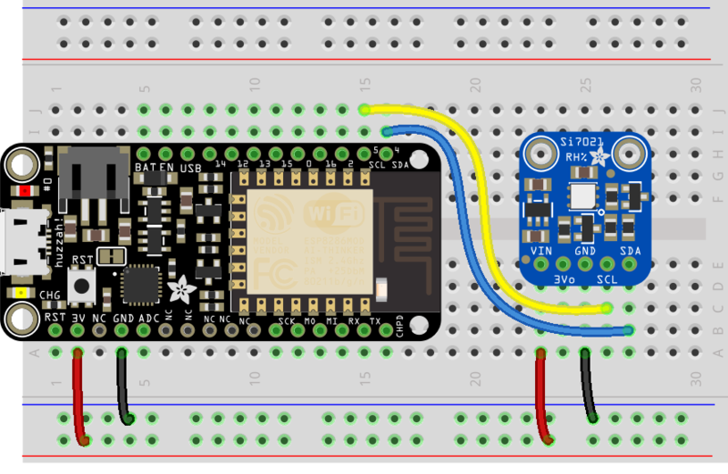
We're going to use the Si7021, a digital temperature and humidity sensor which is less expensive than the popular DHTxx sensors. In addition to being inexpensive, it uses an I2C interface, freeing up digital pins on our Feather HUZZAH microcontroller for other things - like pretty lights and loud buzzers. 

Adafruit Si7021 Temperature & Humidity Sensor Breakout Board
It's summer and you're sweating and your hair's all frizzy and all you really want to know is why the weatherman said this morning that today's relative humidity would...
Out of Stock

Lighting

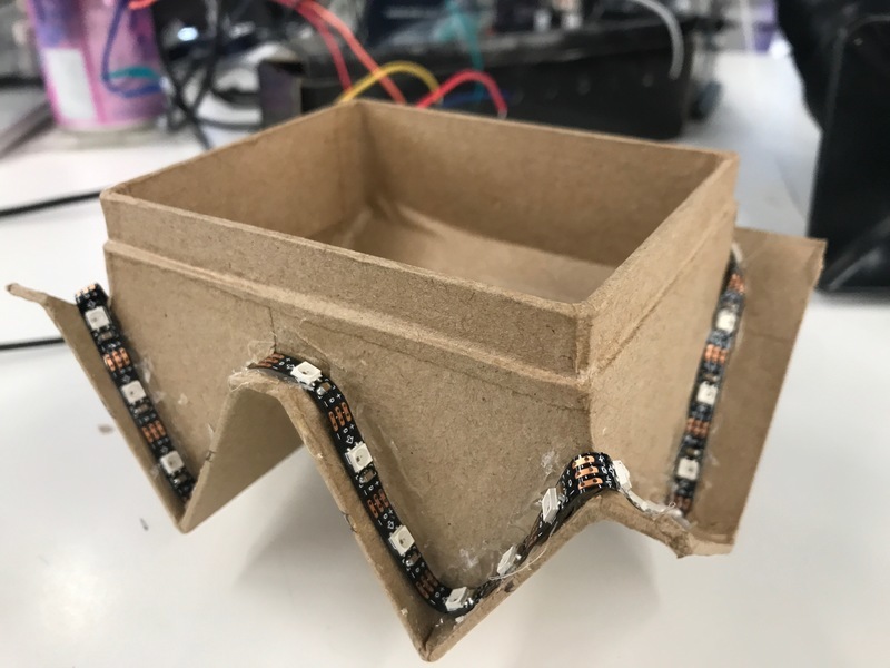
Is anyone home?  We're going to add lighting both inside and outside our house. 

Our lighting system will be comprised of a two different form factors of NeoPixels, which can be chained together and individually addressed, making them perfect for a home-automation system.

For lighting inside the house, we'll be using a NeoPixel Jewel comprised of seven NeoPixels on a round PCB. This light will serve as the lighting inside the house. As a bonus - it looks like a chandelier or a lamp when it's wired using solid-core wire.

NeoPixel Jewel - 7 x 5050 RGB LED wired to Trinket, lit up rainbow
Be the belle of the ball with the NeoPixel Jewel!  We fit seven of our tiny 5050 (5mm x 5mm) smart RGB LEDs onto a beautiful, round PCB with mounting holes and a...
$5.95
In Stock

We'll also be using a 1 meter long Mini Skinny NeoPixel RGB LED Strip to add some lighting around the edges of the roof. This strip is thin enough to wrap around the roof of the house and you can cut it to-length. 

In addition to serving an aesthetic purpose, the outdoor lighting will also be used in later guides which will involve home security. 

Video of an Adafruit NeoPixel Digital RGB LED Strip with all the LEDs illuminating various colors.
So thin. So mini. So teeeeeeny-tiny. It's the 'skinny' version of our classic NeoPixel strips!These NeoPixel strips have 60 digitally-addressable pixel Mini LEDs per...
$99.80
In Stock

Hardware

For the controller, we're going to use a Feather HUZZAH with ESP8266. This board is used by most of our Adafruit IO guides since the ESP8266 is a highly popular and versatile IoT platform. 

This guide is also CircuitPython-compatible. You can use a Raspberry Pi with the IO House series.

Angled shot of rectangular microcontroller.
Feather is the new development board from Adafruit, and like its namesake, it is thin, light, and lets you fly! We designed Feather to be a new standard for portable microcontroller...
$14.95
In Stock

Materials

1 x Breadboard
Half-Size Breadboard
1 x Breadboarding Wire Bundle
You'll want some of these wires to hook up your temperature sensor.
1 x 3-Pin JST Plug
3-pin JST SM Plug + Receptacle Cable Set
1 x Hook-up Wire
Hook-up Wire Spool Set - 22AWG Stranded-Core - 6 x 25ft
1 x Solder
Mini Spool, 100g of 60/40 rosin-core solder.
1 x Right Angle USB Cable
USB Cable which bends at a right angle, can fit easily inside the house.

Tools

The following tools will make this guide much easier to follow. If you do not have access to them, pick some up from the Adafruit Store:

1 x Wire Cutters
Hakko Professional Quality 20-30 AWG Wire Strippers - CSP-30-1
1 x Soldering Station
Hakko FX-888D
1 x Helping Hands
Helping Third Hand Magnifier W/Magnifying Glass Tool

Installing the Roof NeoPixel Strip

First, we're going to test-fit the Mini Skinny NeoPixel strip by lining it around the edge of the roof. Temporarily tape it down to the roof and ensure a snug fit. 

Make sure when you're lining it up that the 2-Pin JST faces the back of the house. This'll keep the wires hidden behind the house.

We're going to cut the NeoPixel strip to fit the exact length of the roofline. There are cut-lines every 7mm along the strip. When you feel satisfied with the roof's NeoPixel strip layout, use a pair of wire cutters to cut along one of these lines.

While the NeoPixel strip will fit underneath the roof with the waterproof sheathing, we want it to have a more flush fit. You can easily cut the sheathing with wire cutters to remove it completely. 

Using a hot glue gun, affix the NeoPixel strip to the roof. Lay down a line of hot glue, and press the strip into the roof edges. Hold it in place for at least five seconds to ensure it sticks and stays. Repeat along all edges of the roof.

After you're finished with all sides of the roof, flip it upside down to let the hot glue dry for an hour or so.

While the roof dries, lets wire up the Si7021 sensor.

Make the following connections between the Feather HUZZAH and the Si7021:

  • Feather Huzzah 3V to Si7021 Vin
  • Feather Huzzah GND to Si7021 GND
  • Feather Huzzah SCL to Si7021 SCL
  • Feather Huzzah SDA to Si7021 SDA

Wiring the NeoPixel Jewel

Start by cutting three lengths of solid-core wire for the power (red), ground (black) and data-in (green). You can use a ruler to measure the height from the breadboard to the middle of the house and cut all three of the wires to the same length.

Strip one end of the red wire and push it through the hole for power (PWR) on the front of the NeoPixel Jewel. Once it's secured, solder it to the pad on the back of the jewel. You can use a pair of helping hands to hold the wire and the jewel so that your hands are free to solder.

Clip the excess wire from the back of the NeoPixel Jewel

And repeat the process for the data and ground wires.

The hot glue should have cured completely by now - let's finish the wiring.

Wiring the Strip and Jewel

Put the roof back on the house. The 2-Pin JST cable bundle should be facing the back of the house. 

While the 2-Pin JST connector connects data and ground, we'd like to include power in our quick-disconnect. To do this, we'll remove the 2-Pin JST connector  and replace it with a 3-Pin JST connector. With a pair of wire cutters, snip off the 2-Pin JST header. 

We'll attach the NeoPixel Jewel to the 3-Pin JST receptacle. While the order of these wires do not matter, make sure you solder Power, Ground and Data Out to the pads on the NeoPixel Jewel.

Arduino Wiring

Make the following connections between the Feather Huzzah and the NeoPixel Jewel:

  • Feather Huzzah 3V to NeoPixel Jewel PWR
  • Feather Huzzah GND to NeoPixel Jewel GND
  • Feather Huzzah Digital Pin 16 to Jewel Din

This wiring diagram also illustrates the wiring for the JST SM plug and receptacle. 

The breadboard wiring should look like the following:

Cut a small, rectangular, hole in the back of the house large enough for the JST plug and a USB Cable.

Place the breadboard inside the house and route the Mini-USB and 3-Pin JST Plug outside of the house.

Connect the JST plug into the receptacle and connect the USB to your computer. 

Next, we'll setup Adafruit IO for this project.

If you are new to using Adafruit IO, you can read all about it in this guide. Go ahead and get your account started.

Visit your Adafruit IO Profile page and click the VIEW AIO KEY button on the left-sidebar.

A window will pop up with your Adafruit IO key and username. Keep a copy of them in a safe place, we'll need them later.

Set Up Feeds

The IO House Series will eventually contain a large amount of Adafruit IO Feeds, which store data. There is one feed per each unique source of data. 

To create a feed for the lights inside the house, navigate to the Adafruit IO Feeds Page and click Actions->Create a New Feed. Name the new feed inside-lights. 

Next, we're going to create the other feeds which will be used by our house. Create a feed for each of the following: temperature, humidityoutside-lights.

Creating an Adafruit IO Dashboard

Next, we'll create an Adafruit IO Dashboard to display and control our feeds. Navigate to the Adafruit IO Dashboard page and click Actions->Create a New Dashboard.

Name this dashboard IO House and click Create. You'll be re-directed to the new Dashboard.

We're going to create two Color Picker blocks to control our inside and outside lighting.

From the IO House Dashboard, click the blue plus icon to add a new block to the dashboard. Then, from the list of available blocks, click the color-picker block.

 Select the indoor-lights feed created earlier.

A new Color Picker block should appear on your dashboard. Repeat these steps to create another color picker for the outside lights. Your dashboard should look like the following:

We also need a way to display our temperature and humidity feeds. We'll create a new block, this time picking the Gauge block, a read-only block that shows a fixed range of values. Select the temperature feed from My Feeds.

We're going to configure the gauge block with a title of temperature, a minimum value of zero degrees Fahrenheit, and a maximum of 220 degrees Fahrenheit.

The gauges in Adafruit IO have recently been improved to include warning values. We'll set them to the freezing point (32 degrees Fahrenheit) and the boiling point (212 degrees Fahrenheit) of water. 

Then, repeat the process of creating a gauge element to display the relative humidity. Your dashboard should look like the following (I added two text blocks to separate the light control and data monitoring parts of the dashboard).

Next, let's set up the Arduino IDE for use with this project.

This guide assumes you've completed the setup required to get your ESP8266 up and running with Arduino IDE and Adafruit IO. 

  • If you haven't yet set up your ESP8266 for use with Adafruit IO and the Arduino IDE, follow along with this guide. The setup only needs to be performed once.

Next, we'll need to install the Adafruit Si7021 library. In the Arduino Library Manager's search-bar, type 
Adafruit Si7021 to search for the library. Click Install. 

We'll need a library to control the NeoPixels. In the search bar, enter Adafruit NeoPixel. Click Install.

Opening the Code

The code for this guide is stored within the latest Adafruit IO Arduino Library release (versions =>2.7.17). From the Arduino IDE, navigate to File->Examples->Adafruit IO Arduino -> io_home_series -> neopixel_and_thermometer.

The IDE should open the sketch (neopixel_and_thermometer.ino) and the configuration file (config.h):

You should now have all the libraries and code required for the IO Home set up. Let's move on to configuring the sketch with your wireless network and Adafruit IO credentials. 

To configure the network settings, click on the config.h tab in the sketch. You will need to set your Adafruit IO username in the IO_USERNAME define, and your Adafruit IO key in the IO_KEY define.

WiFi Config

WiFi is enabled by default in config.h so if you are using one of the supported WiFi boards, you will only need to modify the WIFI_SSID and WIFI_PASS options in the config.h tab.

FONA Config

If you wish to use the FONA 32u4 Feather to connect to Adafruit IO, you will need to first comment out the WiFi support in config.h

Next, remove the comments from both of the FONA config lines in the FONA section of config.h to enable FONA support.

Ethernet Config

If you wish to use the Ethernet Wing to connect to Adafruit IO, you will need to first comment out the WiFi support in config.h

Next, remove the comments from both of the Ethernet config lines in the Ethernet section of config.h to enable Ethernet Wing support.

Next, we will look at how the example sketch works.

We're going to take a walk through the code, load it onto our Feather Huzzah, and interact with it using the Adafruit IO Dashboard we made earlier. 

The code assumes the NeoPixel strip is connected to the Feather Huzzah's digital pin 2 and the NeoPixel jewel is connected to digital pin 16. Both of these pins can be changed by modifying the STRIP_PIN and JEWEL_PIN variables at the beginning of the code.

The code initializes the NeoPixel strip, NeoPixel jewel and the Si7021 sensor objects. It also sets up feeds for the outdoor lights, indoor lights, humidity, and temperature.

// initalize neopixel strip
Adafruit_NeoPixel strip = Adafruit_NeoPixel(STRIP_PIXEL_COUNT, STRIP_PIN, PIXEL_TYPE);
// initalize neopixel jewel
Adafruit_NeoPixel jewel = Adafruit_NeoPixel(JEWEL_PIXEL_COUNT, JEWEL_PIN, PIXEL_TYPE);

// initalize the sensor object
Adafruit_Si7021 sensor = Adafruit_Si7021();

// set up the Adafruit IO feeds
AdafruitIO_Feed *indoorLights = io.feed("indoor-lights");
AdafruitIO_Feed *outdoorLights = io.feed("outdoor-lights");
AdafruitIO_Feed *humidity = io.feed("humidity");
AdafruitIO_Feed *temperature = io.feed("temperature");

The next chunk of code within setup() connects to Adafruit IO, registers two messages handlers to subscribe to the indoorLights and outdoorLights feeds. We also initialize the Si7021 sensor, NeoPixel strip, and NeoPixel jewel. Then, we set all NeoPixels in the house to `off`. 

void setup() {

  // start the serial connection
  Serial.begin(115200);

  // wait for serial monitor to open
  while(! Serial);

  // connect to io.adafruit.com
  Serial.print("Connecting to Adafruit IO");
  io.connect();

  // subscribe to lighting feeds and register message handlers
  indoorLights->onMessage(indoorLightHandler);
  outdoorLights->onMessage(outdoorLightHandler);


  // wait for a connection
  while(io.status() < AIO_CONNECTED) {
    Serial.print(".");
    delay(500);
  }

  // we are connected
  Serial.println();
  Serial.println(io.statusText());

  // initalize the Si7021 sensor
  if (!sensor.begin()) {
    Serial.println("Did not find Si7021 sensor!");
    while (true);
  }
  Serial.println("Si7021 sensor set up!");
  
  // initalize the neopixel strip and jewel.
  strip.begin();
  jewel.begin();

  // set all neopixels on the strip and jewel to `off`.
  strip.show();
  jewel.show();
}

The next chunk of code is the main loop(). First, we call io.run(), which keeps the client connected to Adafruit IO. Then, we query the Si7021 for temperature and humidity values and print them to the Serial Monitor.

The code sends the feeds to Adafruit IO by saving the individual feeds to the data obtained. Finally, it delays the loop by TEMP_DELAY seconds to avoid flooding Adafruit IO with requests - you only get so many requests within a certain time period.

void loop() {
  io.run();

  temperatureData = sensor.readTemperature() * 1.8 + 32;
  humidityData = sensor.readHumidity();
  
  Serial.print("-> Sending Temperature to Adafruit IO: ");
  Serial.println(temperatureData);
  Serial.print("-> Sending Humidity to Adafruit IO: ");
  Serial.println(humidityData);

  // send the state of the feed to adafruit io
  temperature->save(temperatureData);
  humidity->save(humidityData);
  
  // delay the loop to avoid flooding Adafruit IO
  delay(1000*TEMP_DELAY);
}

The code uses have two separate message handlers: one for the outdoor lights and one for the indoor house light. Both of these functions operate in a similar fashion - whenever a message from either the humidity or temperature feed is received from Adafruit IO, the function is called. The function prints out the data value from the Adafruit IO feed as a hexadecimal value and converts it to a RGB value which the NeoPixel light can display.

Then, it sets the color of each individual pixel in the strip from zero to the _PIXEL_COUNT declared at the top of the file. Finally, it calls strip.show() to set the NeoPixel strip to the new color.

void indoorLightHandler(AdafruitIO_Data *data) {
  Serial.print("-> indoor light HEX: ");
  Serial.println(data->value());

  long color = data->toNeoPixel();

  // set the color of each NeoPixel in the jewel
  for(int i=0; i<JEWEL_PIXEL_COUNT; ++i) {
    jewel.setPixelColor(i, color);
  }
  // 'set' the neopixel jewel to the new color
  jewel.show();
}

Compile the code (Sketch->Verify/Compile) and upload (Sketch->Upload) it to your Feather Huzzah. Open the Serial Monitor (Tools->Serial Monitor) and you should see the following output:

Adafruit IO connected.
Si7021 sensor set up!
-> Sending Temperature to Adafruit IO: 75
-> Sending Humidity to Adafruit IO: 41

Navigate to your IO House's Dashboard. The temperature and humidity gauges should display the values from the Arduino Serial Monitor.

Next, we'll test out the inside and outdoor lights from the dashboard. Click (or tap if you're on mobile) the color picker and select a color to set the lights to. You should see either the outdoor or inside lights change depending on which color picker was selected.

This guide is also compatible with the Raspberry Pi using CircuitPython. We're going to build the house's lighting system, wire up the temperature and humidity monitoring circuit, and program it with CircuitPython.

The Pi Zero W has built-in WiFi - which is great for connecting our environmental monitor to Adafruit IO. It's also smaller than a regular Raspberry Pi 3, making it the perfect size to bring with you (monitor the air in the subway station) or stick it in a small corner of your room. 

Angled shot of Raspberry Pi Zero W computer.
If you didn't think that the Raspberry Pi Zero could possibly get any better, then boy do we have a pleasant surprise for you! The new Raspberry Pi Zero W...
$15.00
In Stock

While we could use a breadboard, we'll build our own pHAT for our IO House.

Angled shot of a Adafruit Perma Proto Bonnet on a Pi zero
Design your own Bonnet or pHAT, attach custom circuitry and otherwise dress your Pi Zero with this jaunty prototyping Bonnet kit!To add to the
$4.50
In Stock

Wiring

First, solder the included 20x2 GPIO Header to the Perma Proto Bonnet

Follow the steps on the Putting it Together page until you reach the Arduino Wiring. Instead of following that, use the Python Wiring below:

Python Wiring

Make the following connections between the Si7021 sensor to the Pi:

  • Si7021 Vin to Pi 3V
  • Si7021 GND to Pi Ground
  • Si7021 SCL to Pi SCL
  • Si7021 SDA to Pi SDA

Make the following connections between the NeoPixel Jewel to the Pi:

  • NeoPixel Jewel GND to Pi GND
  • NeoPixel Jewel PWR to Pi 3V
  • NeoPixel Jewel DIN to Pi Digital Pin #18

Make the following connections between the 3-Pin JST Plug to the NeoPixel Jewel:

  • NeoPixel Jewel GND to JST Left Pin
  • NeoPixel Jewel DOUT to JST Middle Pin
  • NeoPixel Jewel PWR to JST Right Pin

Lastly, we'll connect the NeoPixel stick to the 3-Pin JST receptacle:

  • NeoPixel Stick GND to JST Left Pin
  • NeoPixel Stick DI to JST Middle Pin
  • NeoPixel Stick +5V to JST Right Pin

Note: Make sure the NeoPixel strip has arrows pointing upwards, towards the NeoPixel

After wiring it up, plug the 3-Pin JST from your bonnet into the receptacle from the roof.  Plug the Pi's PWR IN into a 5V 2.5A switching power supply

Next, we're going to set up the Raspberry Pi Zero for use with CircuitPython, Adafruit IO, NeoPixels, and the Si7021.

If you're following along with a Raspberry Pi, Beaglebone or any other supported small linux computer, we'll use a special library called adafruit_blinka (named after Blinka, the CircuitPython mascot) to provide the layer that translates the CircuitPython hardware API to whatever library the Linux board provides. It's CircuitPython, on Pi!

If you haven't set up Blinka and/or the Adafruit IO Python Library yet on your Raspberry Pi, follow our guide before continuing with the steps on this page:

Enable I2C

We "talk" to the Si7021 sensor over I2C. To do this, we'll need to set up our Pi's I2C interface. You only have to do this once per Raspberry Pi, the interface is disabled by default.

Once you're done with this and have rebooted, verify you have the I2C devices with the command:

sudo i2cdetect -y 1

The output from running this command should look like the following:

Installing the Adafruit_CircuitPython_Si7021 Sensor Library

We'll need libraries to communicate with the Si7021 sensor. Since we're using Adafruit Blinka (CircuitPython), we can install CircuitPython libraries straight to our Raspberry Pi by using PyPi.

Enter the following command into your terminal to install the adafruit_circuitpython_si7021 library:

sudo pip3 install adafruit-circuitpython-si7021

Installing the Adafruit_CircuitPython_NeoPixel Library

To control our NeoPixels, we'll use the NeoPixel Library for CircuitPython

Enter the following command into your terminal to install the Adafruit_CircuitPython_NeoPixel library:

sudo pip3 install Adafruit_CircuitPython_NeoPixel

Python Code Setup

The code for this guide is located on the Adafruit Learning Guides repository on GitHub under the IO House Series

If you'd like to directly load this code on your Pi, type the following in your terminal and press enter:

git clone https://github.com/adafruit/Adafruit_Learning_System_Guides.git

Then, navigate to the directory where the code for this tutorial is located by typing the following into your terminal:

cd Adafruit_Learning_System_Guides/IO_House_Series/Lights_and_Temp

Let's check to make sure the python code is within that directory. To do this, type ls into your terminal and hit enter. You should see io_house_light_temp.py in this directory:

Before running the code, we need to set our Adafruit IO Key (ADAFRUIT_IO_KEY) and Adafruit IO Username (ADAFRUIT_IO_USERNAME).

To do this, open the code in your text editor of choice (I'm using nano for this example) by entering the following into your terminal:

nano code.py

The code should open in the nano editor. Scroll down to the Adafruit_IO_KEY variable and set it to the your Adafruit IO Key. Then, set the Adafruit_IO_USERNAME to your Adafruit IO Username.

When you're done editing the values, save the file by pressing control + x.

When prompted to save the modified buffer, type and press enter.

At the File Name to Write prompt, press enter and you should be directed back to the terminal.

Next, we're going to learn how the code works and run it from our Pi.

The first large chunk of code creates an instance of the Adafruit IO REST client and sets up the feeds we created earlier in the guide. Then, it creates an I2C interface object and passes it to the sensor.

# Create an instance of the REST client
aio = Client(ADAFRUIT_IO_USERNAME, ADAFRUIT_IO_KEY)

# set up Adafruit IO feeds
temperature = aio.feeds('temperature')
humidity = aio.feeds('humidity')
outdoor_lights = aio.feeds('outdoor-lights')
indoor_lights = aio.feeds('indoor-lights')

# create an i2c interface object
i2c = I2C(SCL, SDA)

# instanciate the sensor object
sensor = adafruit_si7021.SI7021(i2c)

In the while True loop, we obtain the temperature and humidity data from the sensor. Then, we print out and send this data to Adafruit IO using aio.send()

# get data from the si7021 sensor
temperature_data = sensor.temperature
humidity_data = sensor.relative_humidity

# send data to adafruit io
print('> Temperature: ', int(temperature_data))
aio.send(temperature.key, int(temperature_data))
print('> Humidity :', int(humidity_data))
aio.send(temperature.key, int(humidity_data))

Next, we get the hex value from the color picker on the dashboard by using the aio.receive() method. The hex is then converted to individual RGB values using the io-python-client library's helper functions. 

# get the indoor light color picker feed
indoor_light_data = aio.receive(indoor_lights.key)
# convert the hex values to RGB values
red = aio.toRed(indoor_light_data.value)
green = aio.toGreen(indoor_light_data.value)
blue = aio.toBlue(indoor_light_data.value)

To set the color of the NeoPixel Strip or Jewel, we use a loop to set the color of each pixel. 

    # set the jewel's color
    for i in range(JEWEL_PIXEL_COUNT):
        pixels[i] = (red, green, blue)
        pixels.show()

Enter the following command into your terminal to run the code:

sudo python3 io_house_light_temp.py

Note: The NeoPixel library will not work without prepending the script with sudo, as peripherals need to be run as root on the Raspberry Pi.

You should see the code sending the humidity and temperature values to the Adafruit IO dashboard:

Adafruit IO Home: Lights and Climate Control
> Temperature:  24
> Humidity : 57

Visit the IO-Home Dashboard you created on Adafruit IO. You should see the temperature and humidity gauges reflect the values sent from your code.

Change the color picker on the Adafruit IO dashboard and you should see the colors change!

< Indoor Light HEX:  #52ff00
< Outdoor Light HEX:  #000000

Code

# SPDX-FileCopyrightText: 2018 Brent Rubell for Adafruit Industries
#
# SPDX-License-Identifier: MIT

"""
'io_house_light_temp.py'
=======================================
Control lights and monitor temperature
and humidity in a model smart house.

Learning System Guide: https://learn.adafruit.com/adafruit-io-house-lights-and-temperature

Author(s): Brent Rubell for Adafruit Industries, 2018.

Dependencies:
    - Adafruit_Blinka
        (https://github.com/adafruit/Adafruit_Blinka)
    - Adafruit_CircuitPython_SI7021
        (https://github.com/adafruit/Adafruit_CircuitPython_SI7021)
    - Adafruit_CircuitPython_NeoPixel
        (https://github.com/adafruit/Adafruit_CircuitPython_NeoPixel)
"""
# Import standard python modules
import time

# import Adafruit IO REST client
from Adafruit_IO import Client

# import Adafruit Blinka
from busio import I2C
from board import SCL, SDA, D18

# import Adafruit_CircuitPython_Si7021 Library
import adafruit_si7021

# import neopixel library
import neopixel

# `while True` loop delay, in seconds
DELAY_TIME = 5

# number of LED pixels on the NeoPixel Strip
STRIP_LED_COUNT = 34
# number of LED pixels on the NeoPixel Jewel
JEWEL_PIXEL_COUNT = 7

# Set to your Adafruit IO key.
# Remember, your key is a secret,
# so make sure not to publish it when you publish this code!
ADAFRUIT_IO_KEY = 'YOUR_IO_KEY'

# Set to your Adafruit IO username.
# (go to https://accounts.adafruit.com to find your username)
ADAFRUIT_IO_USERNAME = 'YOUR_IO_USERNAME'

# Create an instance of the REST client
aio = Client(ADAFRUIT_IO_USERNAME, ADAFRUIT_IO_KEY)

# set up Adafruit IO feeds
temperature = aio.feeds('temperature')
humidity = aio.feeds('humidity')
outdoor_lights = aio.feeds('outdoor-lights')
indoor_lights = aio.feeds('indoor-lights')

# create an i2c interface object
i2c = I2C(SCL, SDA)

# instanciate the sensor object
sensor = adafruit_si7021.SI7021(i2c)

# set up the NeoPixel strip
pixels = neopixel.NeoPixel(D18, STRIP_LED_COUNT)
pixels.fill((0,0,0))
pixels.show()

print('Adafruit IO Home: Lights and Climate Control')

while True:
    # get data from the si7021 sensor
    temperature_data = sensor.temperature
    humidity_data = sensor.relative_humidity

    # send data to adafruit io
    print('> Temperature: ', int((temperature_data * 1.8)+32))
    aio.send(temperature.key, int(temperature_data * 1.8)+32)
    print('> Humidity :', int(humidity_data))
    aio.send(temperature.key, int(humidity_data))

    # get the indoor light color picker feed
    indoor_light_data = aio.receive(indoor_lights.key)
    print('< Indoor Light HEX: ', indoor_light_data.value)
    # convert the hex values to RGB values
    red = aio.toRed(indoor_light_data.value)
    green = aio.toGreen(indoor_light_data.value)
    blue = aio.toBlue(indoor_light_data.value)

    # set the jewel's color
    for i in range(JEWEL_PIXEL_COUNT):
        pixels[i] = (red, green, blue)
        pixels.show()

    # get the outdoor light color picker feed
    outdoor_light_data = aio.receive(outdoor_lights.key)
    print('< Outdoor Light HEX: ', outdoor_light_data.value)

    # convert the hex values to RGB values
    red = aio.toRed(outdoor_light_data.value)
    green = aio.toGreen(outdoor_light_data.value)
    blue = aio.toBlue(outdoor_light_data.value)

    # set the strip color
    for j in range(JEWEL_PIXEL_COUNT, STRIP_LED_COUNT + JEWEL_PIXEL_COUNT):
        pixels[j] = (red, green, blue)
        pixels.show()

    # delay the loop to avoid timeout from Adafruit IO.
    time.sleep(DELAY_TIME)

This guide was first published on Aug 27, 2018. It was last updated on Apr 16, 2024.