One of the things we baked into CircuitPython is 'HID' (Human Interface Device) control - that means keyboard and mouse capabilities. This means your CircuitPython board can act like a keyboard device and press key commands, or a mouse and have it move the mouse pointer around and press buttons. This is really handy because even if you cannot adapt your software to work with hardware, there's almost always a keyboard interface - so if you want to have a capacitive touch interface for a game, say, then keyboard emulation can often get you going really fast!
This section walks you through the code to create a keyboard or mouse emulator. First we'll go through an example that uses pins on your board to emulate keyboard input. Then, we will show you how to wire up a joystick to act as a mouse, and cover the code needed to make that happen.
CircuitPython Keyboard Emulator
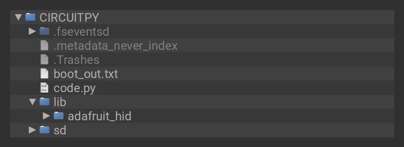
To use with CircuitPython, you need to first install a few libraries, into the lib folder on your CIRCUITPY drive. Then you need to update code.py with the example script.
Thankfully, we can do this in one go. In the example below, click the Download Project Bundle button below to download the necessary libraries and the code.py file in a zip file. Extract the contents of the zip file, open the directory CircuitPython_Essentials/CircuitPython_HID_Keyboard/ and then click on the directory that matches the version of CircuitPython you're using and copy the contents of that directory to your CIRCUITPY drive.
Your CIRCUITPY

# SPDX-FileCopyrightText: 2018 Kattni Rembor for Adafruit Industries
#
# SPDX-License-Identifier: MIT

"""CircuitPython Essentials HID Keyboard example"""
import time

import board
import digitalio
import usb_hid
from adafruit_hid.keyboard import Keyboard
from adafruit_hid.keyboard_layout_us import KeyboardLayoutUS
from adafruit_hid.keycode import Keycode

# A simple neat keyboard demo in CircuitPython

# The pins we'll use, each will have an internal pullup
keypress_pins = [board.A1, board.A2]
# Our array of key objects
key_pin_array = []
# The Keycode sent for each button, will be paired with a control key
keys_pressed = [Keycode.A, "Hello World!\n"]
control_key = Keycode.SHIFT

# The keyboard object!
time.sleep(1)  # Sleep for a bit to avoid a race condition on some systems
keyboard = Keyboard(usb_hid.devices)
keyboard_layout = KeyboardLayoutUS(keyboard)  # We're in the US :)

# Make all pin objects inputs with pullups
for pin in keypress_pins:
    key_pin = digitalio.DigitalInOut(pin)
    key_pin.direction = digitalio.Direction.INPUT
    key_pin.pull = digitalio.Pull.UP
    key_pin_array.append(key_pin)

# For most CircuitPython boards:
led = digitalio.DigitalInOut(board.LED)
# For QT Py M0:
# led = digitalio.DigitalInOut(board.SCK)
led.direction = digitalio.Direction.OUTPUT

print("Waiting for key pin...")

while True:
    # Check each pin
    for key_pin in key_pin_array:
        if not key_pin.value:  # Is it grounded?
            i = key_pin_array.index(key_pin)
            print("Pin #%d is grounded." % i)

            # Turn on the red LED
            led.value = True

            while not key_pin.value:
                pass  # Wait for it to be ungrounded!
            # "Type" the Keycode or string
            key = keys_pressed[i]  # Get the corresponding Keycode or string
            if isinstance(key, str):  # If it's a string...
                keyboard_layout.write(key)  # ...Print the string
            else:  # If it's not a string...
                keyboard.press(control_key, key)  # "Press"...
                keyboard.release_all()  # ..."Release"!

            # Turn off the red LED
            led.value = False

    time.sleep(0.01)
Connect pin A1 or A2 to ground, using a wire or alligator clip, then disconnect it to send the key press "A" or the string "Hello world!"
This wiring example shows A1 and A2 connected to ground.
Remember, on Trinket, A1 and A2 are labeled 2 and 0! On other boards, you will have A1 and A2 labeled as expected.
Create the Objects and Variables
First, we assign some variables for later use. We create three arrays assigned to variables: keypress_pins, key_pin_array, and keys_pressed. The first is the pins we're going to use. The second is empty because we're going to fill it later. The third is what we would like our "keyboard" to output - in this case the letter "A" and the phrase, "Hello world!". We create our last variable assigned to control_key which allows us to later apply the shift key to our keypress. We'll be using two keypresses, but you can have up to six keypresses at once.
Next keyboard and keyboard_layout objects are created. We only have US right now (if you make other layouts please submit a GitHub pull request!). The time.sleep(1) avoids an error that can happen if the program gets run as soon as the board gets plugged in, before the host computer finishes connecting to the board.
Then we take the pins we chose above, and create the pin objects, set the direction and give them each a pullup. Then we apply the pin objects to key_pin_array so we can use them later.
Next we set up the little red LED to so we can use it as a status light.
The last thing we do before we start our loop is print, "Waiting for key pin..." so you know the code is ready and waiting!
The Main Loop
Inside the loop, we check each pin to see if the state has changed, i.e. you connected the pin to ground. Once it changes, it prints, "Pin # grounded." to let you know the ground state has been detected. Then we turn on the red LED. The code waits for the state to change again, i.e. it waits for you to unground the pin by disconnecting the wire attached to the pin from ground.
Then the code gets the corresponding keys pressed from our array. If you grounded and ungrounded A1, the code retrieves the keypress a, if you grounded and ungrounded A2, the code retrieves the string, "Hello world!"
If the code finds that it's retrieved a string, it prints the string, using the keyboard_layout to determine the keypresses. Otherwise, the code prints the keypress from the control_key and the keypress "a", which result in "A". Then it calls keyboard.release_all(). You always want to call this soon after a keypress or you'll end up with a stuck key which is really annoying!
Instead of using a wire to ground the pins, you can try wiring up buttons like we did in CircuitPython Digital In & Out. Try altering the code to add more pins for more keypress options!
Non-US Keyboard Layouts
The code above uses KeyboardLayoutUS. If you would like to emulate a non-US keyboard, a number of other keyboard layout classes are available.
CircuitPython Mouse Emulator
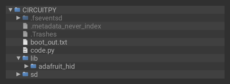
To use with CircuitPython, you need to first install a few libraries, into the lib folder on your CIRCUITPY drive. Then you need to update code.py with the example script.
Thankfully, we can do this in one go. In the example below, click the Download Project Bundle button below to download the necessary libraries and the code.py file in a zip file. Extract the contents of the zip file, open the directory CircuitPython_Essentials/CircuitPython_HID_Mouse/ and then click on the directory that matches the version of CircuitPython you're using and copy the contents of that directory to your CIRCUITPY drive.
Your CIRCUITPY

# SPDX-FileCopyrightText: 2018 Kattni Rembor for Adafruit Industries
#
# SPDX-License-Identifier: MIT

"""CircuitPython Essentials HID Mouse example"""
import time
import analogio
import board
import digitalio
import usb_hid
from adafruit_hid.mouse import Mouse

mouse = Mouse(usb_hid.devices)

x_axis = analogio.AnalogIn(board.A0)
y_axis = analogio.AnalogIn(board.A1)
select = digitalio.DigitalInOut(board.A2)
select.direction = digitalio.Direction.INPUT
select.pull = digitalio.Pull.UP

pot_min = 0.00
pot_max = 3.29
step = (pot_max - pot_min) / 20.0


def get_voltage(pin):
    return (pin.value * 3.3) / 65536


def steps(axis):
    """ Maps the potentiometer voltage range to 0-20 """
    return round((axis - pot_min) / step)


while True:
    x = get_voltage(x_axis)
    y = get_voltage(y_axis)

    if select.value is False:
        mouse.click(Mouse.LEFT_BUTTON)
        time.sleep(0.2)  # Debounce delay

    if steps(x) > 11.0:
        # print(steps(x))
        mouse.move(x=1)
    if steps(x) < 9.0:
        # print(steps(x))
        mouse.move(x=-1)

    if steps(x) > 19.0:
        # print(steps(x))
        mouse.move(x=8)
    if steps(x) < 1.0:
        # print(steps(x))
        mouse.move(x=-8)

    if steps(y) > 11.0:
        # print(steps(y))
        mouse.move(y=-1)
    if steps(y) < 9.0:
        # print(steps(y))
        mouse.move(y=1)

    if steps(y) > 19.0:
        # print(steps(y))
        mouse.move(y=-8)
    if steps(y) < 1.0:
        # print(steps(y))
        mouse.move(y=8)
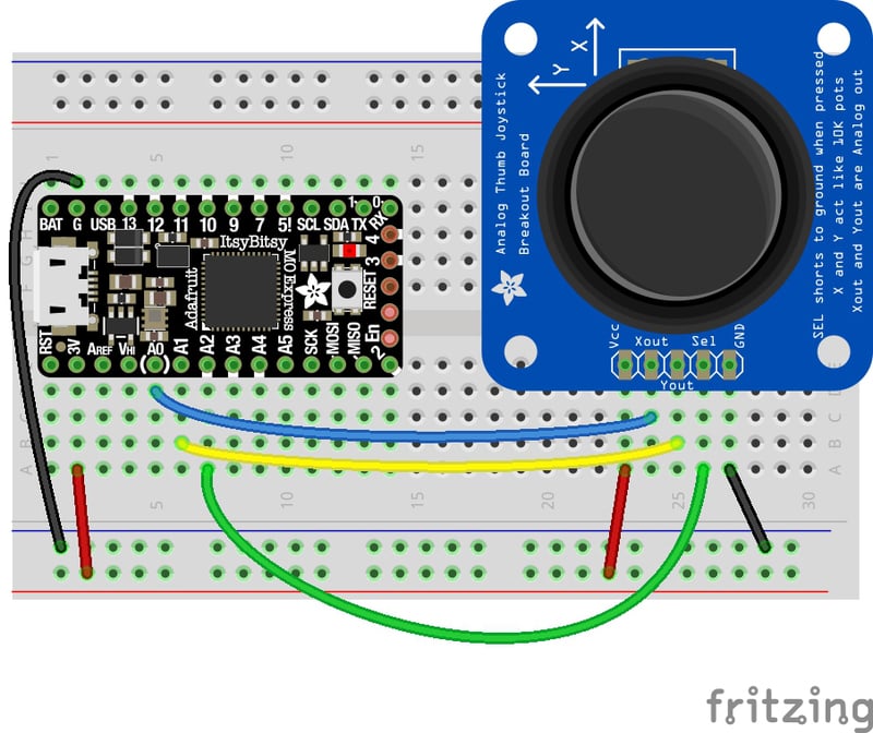
For this example, we've wired up a 2-axis thumb joystick with a select button. We use this to emulate the mouse movement and the mouse left-button click. To wire up this joytick:
- Connect VCC on the joystick to the 3V on your board. Connect ground to ground.
- Connect Xout on the joystick to pin A0 on your board.
- Connect Yout on the joystick to pin A1 on your board.
- Connect Sel on the joystick to pin A2 on your board.
Remember, Trinket's pins are labeled differently. Check the Trinket Pinouts page to verify your wiring.
To use this demo, simply move the joystick around. The mouse will move slowly if you move the joystick a little off center, and more quickly if you move it as far as it goes. Press down on the joystick to click the mouse. Awesome! Now let's take a look at the code.
Create the Objects and Variables
First we create the mouse object.
Next, we set x_axis and y_axis to pins A0 and A1. Then we set select to A2, set it as input and give it a pullup.
The x and y axis on the joystick act like 2 potentiometers. We'll be using them just like we did in CircuitPython Analog In. We set pot_min and pot_max to be the minimum and maximum voltage read from the potentiometers. We assign step = (pot_max - pot_min) / 20.0 to use in a helper function.
CircuitPython HID Mouse Helpers
First we have the get_voltage() helper so we can get the correct readings from the potentiometers. Look familiar? We learned about it in Analog In.
Second, we have steps(axis). To use it, you provide it with the axis you're reading. This is where we're going to use the step variable we assigned earlier. The potentiometer range is 0-3.29. This is a small range. It's even smaller with the joystick because the joystick sits at the center of this range, 1.66, and the + and - of each axis is above and below this number. Since we need to have thresholds in our code, we're going to map that range of 0-3.29 to while numbers between 0-20.0 using this helper function. That way we can simplify our code and use larger ranges for our thresholds instead of trying to figure out tiny decimal number changes.
Main Loop
First we assign x and y to read the voltages from x_axis and y_axis.
Next, we check to see when the state of the select button is False. It defaults to True when it is not pressed, so if the state is False, the button has been pressed. When it's pressed, it sends the command to click the left mouse button. The time.sleep(0.2) prevents it from reading multiple clicks when you've only clicked once.
Then we use the steps() function to set our mouse movement. There are two sets of two if statements for each axis. Remember that 10 is the center step, as we've mapped the range 0-20. The first set for each axis says if the joystick moves 1 step off center (left or right for the x axis and up or down for the y axis), to move the mouse the appropriate direction by 1 unit. The second set for each axis says if the joystick is moved to the lowest or highest step for each axis, to move the mouse the appropriate direction by 8 units. That way you have the option to move the mouse slowly or quickly!
To see what step the joystick is at when you're moving it, uncomment the print statements by removing the # from the lines that look like # print(steps(x)), and connecting to the serial console to see the output. Consider only uncommenting one set at a time, or you end up with a huge amount of information scrolling very quickly, which can be difficult to read!


