One of our favorite Feathers, the Feather M4 Express, gets a glow-up here with an upgrade to the SAME51 chipset which has built-in CAN bus support!  Like its SAMD51 cousin, the ATSAME51J19 comes with a 120MHz Cortex M4 with floating point support and 512KB Flash and 192KB RAM. Your code will zig and zag and zoom, and with a bunch of extra peripherals for support, this will for sure be your favorite new chipset for CAN interfacing projects.

At the end of the board we have placed a CAN transceiver chip as well as a 5V converter to generate 5V power to the transceiver even when running on battery. The two CAN signal lines and ground reference signal are available on a 3-pin 3.5mm terminal block. The chip and booster can be put to sleep for power saving. The built in CAN can read or write packets and has support in both Arduino and CircuitPython.

And best of all, it's a Feather - so you know it will work with all our FeatherWings! What a great way to quickly get up and running. It's even pin-compatible with the original Feather M4.

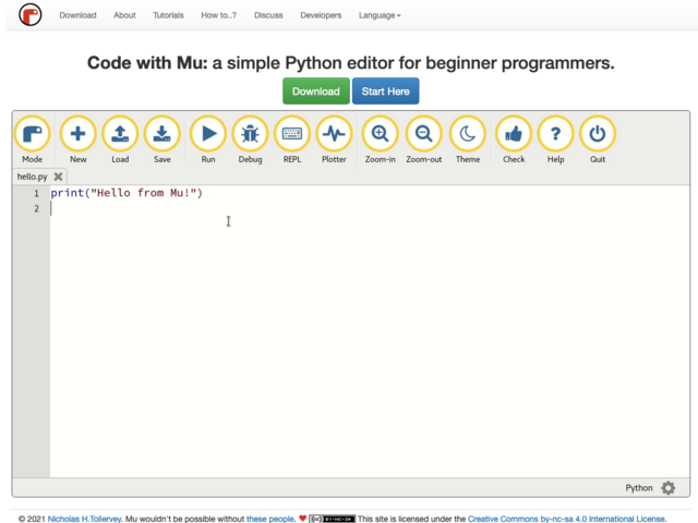
The most exciting part of the Feather M4 CAN is that while you can use it with the Arduino IDE - and it's bonkers fast when you do, you can use it with CircuitPython as well. When you plug it in, it will show up as a very small disk drive with main.py on it. Edit main.py with your favorite text editor to build your project using Python, the most popular programming language. No installs, IDE or compiler needed, so you can use it on any computer, even ChromeBooks or computers you can't install software on. When you're done, unplug the Feather and your code will go with you.

Here are some of the updates you can look forward to when using Feather M4 CAN:

  • Measures 2.0" x 0.9" x 0.28" (50.8mm x 22.8mm x 7mm) without headers soldered in
  • Light as a (large?) feather - 5 grams
  • ATSAME51 32-bit Cortex M4 core running at 120 MHz, 32-bit, 3.3V logic and power
  • Hardware CAN bus support with built-in transceiver, 5V booster and terminal connection.
  • Floating point support with Cortex M4 DSP instructions
  • 512 KB flash, 192 KB RAM
  • 2 MB SPI FLASH chip for storing files and CircuitPython code storage.
  • No EEPROM
  • 32.768 KHz crystal for clock generation & RTC
  • 3.3V regulator with 500mA peak current output
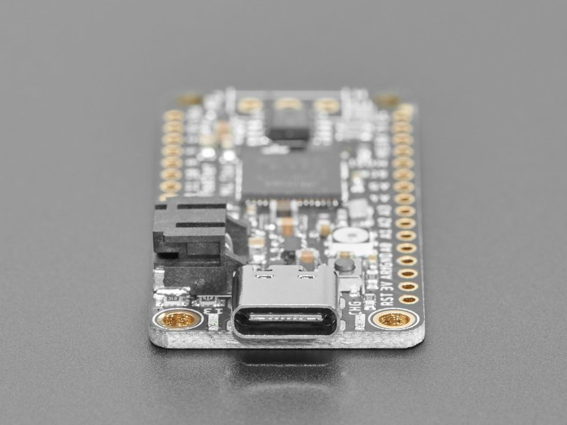
  • USB Type C connector for USB native support, comes with USB bootloader and serial port debugging
  • Built in crypto engines with AES (256 bit), true RNG, Pubkey controller
  • Tons of GPIO! 21 x GPIO pins with following capabilities:
    • Dual 1 MSPS 12 bit true analog DAC (A0 and A1) - can be used to play 12-bit stereo audio clips
    • Dual 1 MSPS 12 bit ADC (6 analog pins some on ADC1 and some on ADC2)
    • 6 x hardware SERCOM - Native hardware SPI, I2C and Serial all available
    • 16 x PWM outputs - for servos, LEDs, etc
    • I2S input and output
    • 8-bit Parallel capture controller (for camera/video in)
  • Built in 100mA lipoly charger with charging status indicator LED
  • Pin #13 red LED for general purpose blinking
  • Power/enable pin
  • 4 mounting holes
  • Reset button

The Feather M4 Can Express also comes with a Mini NeoPixel and 2 MB SPI Flash storage. You can use the SPI Flash storage like a very tiny hard drive. When used in CircuitPython, the 2 MB flash acts as storage for all your scripts, libraries and files. When used in Arduino, you can read/write files to it, like a little datalogger or SD card, and then with our helper program, access the files over USB.

Easy reprogramming: the Feather M4 CAN comes pre-loaded with the UF2 bootloader, which looks like a USB storage key. Simply drag firmware on to program, no special tools or drivers needed! It can be used to load up CircuitPython or Arduino IDE (it is bossa-compatible)

Comes fully assembled and tested, with the UF2 USB bootloader. We also toss in some headers so you can solder it in and plug into a solderless breadboard. 

Lipoly battery and USB cable not included (but we do have lots of options in the shop if you'd like!)

The Feather M4 CAN Express is loaded with microcontroller and CAN goodness. It also has many pins and ports. Let's take a tour!

If you've used the Feather M4 (non-CAN version) - please note that the pinouts for the CAN version use the same exact GPIO's for all exposed pins. This makes the CAN Feather M4 work with all of the GPIO-specific accessories like RGB matrix drivers, NeoPXL8 wings, etc.

Power

  • USB C port - This is used for both powering and programming the board. You can power it with any USB C cable and will request 5V from a USB C PD. When USB is plugged in it will charge the Lipoly battery.
  • GND - this is the common ground for all power and logic
  • BAT - this is the positive voltage to/from the JST jack for the optional Lipoly battery
  • USB - this is the positive voltage to/from the USB C jack if connected
  • EN - this is the 3.3V regulator's enable pin. It's pulled up, so connect to ground to disable the 3.3V regulator
  • 3V - this is the output from the 3.3V regulator, it can supply 500mA peak

CAN Bus

The SAMDE51 has built in hardware CAN bus support, but you still need a transceiver.

We use a 3V-logic compatible transceiver (the 8-SOIC chip).

Right above it, there is a small 3V->5V switched-capacitor boost converter so that the output CAN signals are +-5V.

By default both the boost converter and the transceiver are disabled. The boost-enable pin is connected to pin #4 (BOOST_ENABLE in CircuitPython), and the transceiver enable (standby) is on a pin named PIN_CAN_STANDBY

Here is Arduino code to turn on both the transceiver and booster:

pinMode(PIN_CAN_STANDBY, OUTPUT);
digitalWrite(PIN_CAN_STANDBY, false); // turn off STANDBY
pinMode(4, OUTPUT);
digitalWrite(4, true); // turn on booster

In CircuitPython you can use this snippet to enable

# If the CAN transceiver has a standby pin, bring it out of standby mode
if hasattr(board, 'CAN_STANDBY'):
    standby = digitalio.DigitalInOut(board.CAN_STANDBY)
    standby.switch_to_output(False)
 
# If the CAN transceiver is powered by a boost converter, turn on its supply
if hasattr(board, 'BOOST_ENABLE'):
    boost_enable = digitalio.DigitalInOut(board.BOOST_ENABLE)
    boost_enable.switch_to_output(True)

The board has a 120 ohm terminator connected between H and L. You can disable (remove) the terminator by cutting the Trm jumper, if your bus is already terminated!

Logic Pins

This is the general purpose I/O pin set for the microcontroller.
All logic is 3.3V
Nearly all pins can do PWM output
All pins can be interrupt inputs

  • #0 / RX - GPIO #0, also receive (input) pin for Serial1 (hardware UART). Also PWM out
  • #1 / TX - GPIO #1, also transmit (output) pin for Serial1. PWM out
  • SDA - the I2C (Wire) data pin. There's no pull up on this pin by default so when using with I2C, you may need a 2.2K-10K pullup. Also GPIO #21. Also PWM out
  • SCL - the I2C (Wire) clock pin. There's no pull up on this pin by default so when using with I2C, you may need a 2.2K-10K pullup. Also GPIO #22. Also PWM out
  • #4 - GPIO #4, PWM out
  • #5 - GPIO #5, PWM out
  • #6 - GPIO #6, PWM out
  • #9 - GPIO #9, PWM out
  • #10 - GPIO #10, PWM out
  • #11 - GPIO #11, PWM out
  • #12 - GPIO #12, PWM out
  • #13 - GPIO #13, PWM out and is connected to the red LED next to the USB jack
  • SCK/MOSI/MISO - These are the hardware SPI pins, you can use them as everyday GPIO #25/#24/#23 pins (but recommend keeping them free as they are best used for hardware SPI connections for high speed.)

Analog Pins:

  • A0 - This pin is analog input A0 but is also an analog output due to having a DAC (digital-to-analog converter). You can set the raw voltage to anything from 0 to 3.3V, unlike PWM outputs this is a true analog output
  • A1 - This pin is analog input  A1 but is also an analog output due to having a DAC (digital-to-analog converter). This is the second DAC, and is 'independent' of A0. You can set the raw voltage to anything from 0 to 3.3V, unlike PWM outputs this is a true analog output. Also can do PWM.
  • A2 thru A5 - These are each analog input as well as digital I/O pins. These pins can also do PWM.

I2S Pins:

  • #1/Tx - I2S bit_clock pin.
  • #10 - I2S word_select pin.
  • #11 - I2S data pin.

These pins are available in CircuitPython under the board module. Names that start with # are prefixed with D and other names are as is. So #0 / RX above is available as board.D0 and board.RX for example.

Parallel Capture Peripheral

There's a 'camera' input peripheral you can use with some camera chips to capture video with 8-bit data width. We thought this was neat so we made sure all those pins were available. Here are the PCC pins (left) and the Feather M4 pins it's mapped to. Unlike other peripherals, you cannot mux these signals to other pins!

  • DEN1: SDA
  • DEN2: SCL
  • CLK: D6
  • D0: D11
  • D1: D13
  • D2: D10
  • D3: D12
  • D4: MISO
  • D5: D5
  • D6: MOSI
  • D7: SCK

NeoPixel and LEDs

As part of the 'Express' series of boards, the Feather M4 CAN Express is designed for use with CircuitPython. To make that easy, we have added two extra parts to this Feather M4: a mini NeoPixel (addressable RGB LED) and a 2 MB QSPI (Quad SPI) Flash chip. There is also the little red LED, and a yellow charge LED.

NeoPixel LED - connected to pin #8 in Arduino, so just use our NeoPixel library and set it up as a single-LED strand on pin 8. In CircuitPython, the NeoPixel is board.NEOPIXEL and the library for it is here and in the bundle.

Unlike most other boards the NeoPixel is not powered by the 3.3V power supply - instead we power it from a separate GPIO pin. This lets us turn off the NeoPixel completely, removing the ~1mA quiescent current. To enable the NeoPixel, set the NEOPIXEL_POWER (CircuitPython) or PIN_NEOPIXEL_POWER (Arduino) to be an OUTPUT and HIGH. To disable it, set it to be an OUTPUT and LOW. (When used as a status LED, CircuitPython will automatically enable the power)

The NeoPixel is also used by the bootloader to let you know if the device has enumerated correctly (green) or USB failure (red). In CircuitPython, the LED is used to indicate the runtime status.

  • Red LED - connected to pin #13. It is user-controllable through code.
  • CHG LED - This LED is lit up when a battery is charging. If there is no battery attached, the yellow LED will flicker (it's looking for a battery!)

QSPI Flash

  • QSPI Flash - connected to 6 pins that are not brought out on the GPIO pads. This way you don't have to worry about the SPI flash colliding with other devices on the main SPI connection.

QSPI is neat because it allows you to have 4 data in/out lines instead of just SPI's single line in and single line out. This means that QSPI is at least 4 times faster. But in reality is at least 10x faster because you can clock the QSPI peripheral much faster than a plain SPI peripheral

However, the QSPI port is not also on an SERCOM. So, you have to either use the QSPI peripheral or bitbang SPI if you want to talk to the chip. We have an Arduino library here which provides QSPI interfacing for Arduino. In CircuitPython, the QSPI flash is used natively by the interpretter and is read-only to user code, instead the Flash just shows up as the writeable disk drive!

Other Pins

  • RST - this is the Reset pin, tie to ground to manually reset the ATSAMD51, as well as launch the bootloader manually
  • ARef - the analog reference pin. Normally the reference voltage is the same as the chip logic voltage (3.3V) but if you need an alternative analog reference, connect it to this pin and select the external AREF in your firmware. Can't go higher than 3.3V!
On the Feather M4 CAN Express, at least for now, AREF is tied to 3.3V due to a silicon v0 bug that does not allow the DACs to work unless AREF is connected to 3.3V. You cut the bottom jumper if you need a different AREF voltage but note that this may change DAC range!

Debugging Interface

If you'd like to do more advanced development, trace-debugging, or not use the bootloader, we have the SWD interface exposed. You'll have to solder to the two SWDIO/SWCLK pads on the bottom:

Battery + USB Power

We wanted to make our Feather boards easy to power both when connected to a computer as well as via battery.

There's two ways to power a Feather:

  1. You can connect with a USB cable (just plug into the jack) and the Feather will regulate the 5V USB down to 3.3V.
  2. You can also connect a 4.2/3.7V Lithium Polymer (LiPo/LiPoly) or Lithium Ion (LiIon) battery to the JST jack. This will let the Feather run on a rechargeable battery.

When the USB power is powered, it will automatically switch over to USB for power, as well as start charging the battery (if attached). This happens 'hot-swap' style so you can always keep the LiPoly connected as a 'backup' power that will only get used when USB power is lost.

The JST connector polarity is matched to Adafruit LiPoly batteries. Using wrong polarity batteries can destroy your Feather. Many customers try to save money by purchasing Lipoly batteries from Amazon only to find that they plug them in and the Feather is destroyed!

The above shows the USB-C jack (left), LiPoly JST jack (top left), as well as the changeover diode (just to the right of the JST jack) and the LiPoly charging circuitry (to the right of the JST jack).

There's also a CHG LED next to the USB jack, which will light up while the battery is charging. This LED might also flicker if the battery is not connected, it's normal.

The charge LED is automatically driven by the LiPoly charger circuit. It will try to detect a battery and is expecting one to be attached. If there isn't one it may flicker once in a while when you use power because it's trying to charge a (non-existent) battery. It's not harmful, and it's totally normal!

Power Supplies

You have a lot of power supply options here! We bring out the BAT pin, which is tied to the LiPoly JST connector, as well as USB which is the +5V from USB if connected. We also have the 3V pin which has the output from the 3.3V regulator. We use a 500mA peak regulator. While you can get 500mA from it, you can't do it continuously from 5V as it will overheat the regulator.

It's fine for, say, powering an ESP8266 WiFi chip or XBee radio though, since the current draw is 'spikey' & sporadic.

Measuring Battery

If you're running off of a battery, chances are you wanna know what the voltage is at! That way you can tell when the battery needs recharging. LiPoly batteries are 'maxed out' at 4.2V and stick around 3.7V for much of the battery life, then slowly sink down to 3.2V or so before the protection circuitry cuts it off. By measuring the voltage you can quickly tell when you're heading below 3.7V.

To make this easy we stuck a double-100K resistor divider on the BAT pin, and connected it to A6 which is not exposed on the feather breakout.

In Arduino, you can read this pin's voltage, then double it, to get the battery voltage.

// Arduino Example Code snippet

#define VBATPIN A6

float measuredvbat = analogRead(VBATPIN);
measuredvbat *= 2;    // we divided by 2, so multiply back
measuredvbat *= 3.3;  // Multiply by 3.3V, our reference voltage
measuredvbat /= 1024; // convert to voltage
Serial.print("VBat: " ); Serial.println(measuredvbat);

For CircuitPython, we've written a get_voltage() helper function to do the math for you. All you have to do is call the function, provide the pin and print the results.

import board
from analogio import AnalogIn

vbat_voltage = AnalogIn(board.VOLTAGE_MONITOR)


def get_voltage(pin):
    return (pin.value * 3.3) / 65536 * 2


battery_voltage = get_voltage(vbat_voltage)
print("VBat voltage: {:.2f}".format(battery_voltage))

ENable pin

If you'd like to turn off the 3.3V regulator, you can do that with the EN(able) pin. Simply tie this pin to Ground and it will disable the 3V regulator. The BAT and USB pins will still be powered.

Alternative Power Options

The two primary ways for powering a feather are a 3.7/4.2V LiPo battery plugged into the JST port or a USB power cable.

If you need other ways to power the Feather, here's what we recommend:

Here's what you cannot do:

  • Do not use alkaline or NiMH batteries and connect to the battery port - this will destroy the LiPoly charger and there's no way to disable the charger
  • Do not use 7.4V RC batteries on the battery port - this will destroy the board

The Feather is not designed for external power supplies - this is a design decision to make the board compact and low cost. It is not recommended, but technically possible:

  • Connect an external 3.3V power supply to the 3V and GND pins. Not recommended, this may cause unexpected behavior and the EN pin will no longer work. Also this doesn't provide power on BAT or USB and some Feathers/Wings use those pins for high current usages. You may end up damaging your Feather.
  • Connect an external 5V power supply to the USB and GND pins. Not recommended, this may cause unexpected behavior when plugging in the USB port because you will be back-powering the USB port, which could confuse or damage your computer.

The first thing you will need to do is to download the latest release of the Arduino IDE. You will need to be using version 1.8 or higher for this guide

After you have downloaded and installed the latest version of Arduino IDE, you will need to start the IDE and navigate to the Preferences menu. You can access it from the File menu in Windows or Linux, or the Arduino menu on OS X.

A dialog will pop up just like the one shown below.

We will be adding a URL to the new Additional Boards Manager URLs option. The list of URLs is comma separated, and you will only have to add each URL once. New Adafruit boards and updates to existing boards will automatically be picked up by the Board Manager each time it is opened. The URLs point to index files that the Board Manager uses to build the list of available & installed boards.

To find the most up to date list of URLs you can add, you can visit the list of third party board URLs on the Arduino IDE wiki. We will only need to add one URL to the IDE in this example, but you can add multiple URLS by separating them with commas. Copy and paste the link below into the Additional Boards Manager URLs option in the Arduino IDE preferences.

https://adafruit.github.io/arduino-board-index/package_adafruit_index.json

Here's a short description of each of the Adafruit supplied packages that will be available in the Board Manager when you add the URL:

  • Adafruit AVR Boards - Includes support for Flora, Gemma, Feather 32u4, ItsyBitsy 32u4, Trinket, & Trinket Pro.
  • Adafruit SAMD Boards - Includes support for Feather M0 and M4, Metro M0 and M4, ItsyBitsy M0 and M4, Circuit Playground Express, Gemma M0 and Trinket M0
  • Arduino Leonardo & Micro MIDI-USB - This adds MIDI over USB support for the Flora, Feather 32u4, Micro and Leonardo using the arcore project.

If you have multiple boards you want to support, say ESP8266 and Adafruit, have both URLs in the text box separated by a comma (,)

Once done click OK to save the new preference settings. Next we will look at installing boards with the Board Manager.

Now continue to the next step to actually install the board support package!

Adafruit boards that use ATSAMD21 ("M0") or ATSAMD51 ("M4") chips are easy to get working with the Arduino IDE. Most libraries (including the popular ones like NeoPixels and display) will work with those boards, especially devices & sensors that use I2C or SPI.

Now that you have added the appropriate URLs to the Arduino IDE preferences in the previous page, you can open the Boards Manager by navigating to the Tools->Board menu.

Once the Board Manager opens, click on the category drop down menu on the top left hand side of the window and select All. You will then be able to select and install the boards supplied by the URLs added to the preferences.

Remember you need SETUP the Arduino IDE to support our board packages - see the previous page on how to add adafruit's URL to the preferences

Install SAMD Support

First up, install the latest Arduino SAMD Boards (version 1.6.11 or later)

You can type Arduino SAMD in the top search bar, then when you see the entry, click Install

Install Adafruit SAMD

Next you can install the Adafruit SAMD package to add the board file definitions

Make sure you have Type All selected to the left of the Filter your search... box

You can type Adafruit SAMD in the top search bar, then when you see the entry, click Install

Quit and reopen the Arduino IDE to ensure that all of the boards are properly installed. You should now be able to select and upload to the new boards listed in the Tools->Board menu.

Select the matching board, the current options are:

  • Feather M0 (for use with any Feather M0 other than the Express)
  • Feather M0 Express
  • Metro M0 Express
  • Circuit Playground Express
  • Gemma M0
  • Trinket M0
  • QT Py M0
  • ItsyBitsy M0
  • Hallowing M0
  • Crickit M0 (this is for direct programming of the Crickit, which is probably not what you want! For advanced hacking only)
  • Metro M4 Express
  • Grand Central M4 Express
  • ItsyBitsy M4 Express
  • Feather M4 Express
  • Trellis M4 Express
  • PyPortal M4
  • PyPortal M4 Titano
  • PyBadge M4 Express
  • Metro M4 Airlift Lite
  • PyGamer M4 Express
  • MONSTER M4SK
  • Hallowing M4
  • MatrixPortal M4
  • BLM Badge

Windows 7 and 8.1

Windows 7 and Windows 8.1 have reached end-of-life and are no longer supported. They required driver installation. A limited set of drivers is available for older boards, but drivers for most newer boards are not available.

Blink

Now you can upload your first blink sketch!

Plug in the SAMD21 M0 or SAMD51 M4 board, and wait for it to be recognized by the OS (just takes a few seconds). It will create a serial/COM port, you can now select it from the drop-down, it'll even be 'indicated' as Trinket/Gemma/Metro/Feather/ItsyBitsy/QT Py/Trellis or whatever the board is named!

A few boards, such as the QT Py SAMD21, Trellis M4 Express, and certain Trinkey boards, do not have an onboard pin 13 LED. You can follow this section to practice uploading but you won't see an LED blink!

Now load up the Blink example

// the setup function runs once when you press reset or power the board
void setup() {
  // initialize digital pin 13 as an output.
  pinMode(13, OUTPUT);
}

// the loop function runs over and over again forever
void loop() {
  digitalWrite(13, HIGH);   // turn the LED on (HIGH is the voltage level)
  delay(1000);              // wait for a second
  digitalWrite(13, LOW);    // turn the LED off by making the voltage LOW
  delay(1000);              // wait for a second
}

And click upload! That's it, you will be able to see the LED blink rate change as you adapt the delay() calls.

If you are having issues, make sure you selected the matching Board in the menu that matches the hardware you have in your hand.

Successful Upload

If you have a successful upload, you'll get a bunch of red text that tells you that the device was found and it was programmed, verified & reset

After uploading, you may see a message saying "Disk Not Ejected Properly" about the ...BOOT drive. You can ignore that message: it's an artifact of how the bootloader and uploading work.

Compilation Issues

If you get an alert that looks like

Cannot run program "{runtime.tools.arm-none-eabi-gcc.path}\bin\arm-non-eabi-g++"

Make sure you have installed the Arduino SAMD boards package, you need both Arduino & Adafruit SAMD board packages

Manually bootloading

If you ever get in a 'weird' spot with the bootloader, or you have uploaded code that crashes and doesn't auto-reboot into the bootloader, click the RST button twice (like a double-click)to get back into the bootloader.

The red LED will pulse and/or RGB LED will be green, so you know that its in bootloader mode.

Once it is in bootloader mode, you can select the newly created COM/Serial port and re-try uploading.

You may need to go back and reselect the 'normal' USB serial port next time you want to use the normal upload.

The ATSAMD21 and 51 are very nice little chips, but fairly new as Arduino-compatible cores go. Most sketches & libraries will work but here’s a collection of things we noticed.

The notes below cover a range of Adafruit M0 and M4 boards, but not every rule will apply to every board (e.g. Trinket and Gemma M0 do not have ARef, so you can skip the Analog References note!).

Analog References

If you'd like to use the ARef pin for a non-3.3V analog reference, the code to use is analogReference(AR_EXTERNAL) (it's AR_EXTERNAL not EXTERNAL)

Pin Outputs & Pullups

The old-style way of turning on a pin as an input with a pullup is to use

pinMode(pin, INPUT)
digitalWrite(pin, HIGH)

This is because the pullup-selection register on 8-bit AVR chips is the same as the output-selection register.

For M0 & M4 boards, you can't do this anymore! Instead, use:

pinMode(pin, INPUT_PULLUP)

Code written this way still has the benefit of being backwards compatible with AVR. You don’t need separate versions for the different board types.

Serial vs SerialUSB

99.9% of your existing Arduino sketches use Serial.print to debug and give output. For the Official Arduino SAMD/M0 core, this goes to the Serial5 port, which isn't exposed on the Feather. The USB port for the Official Arduino M0 core is called SerialUSB instead.

In the Adafruit M0/M4 Core, we fixed it so that Serial goes to USB so it will automatically work just fine.

However, on the off chance you are using the official Arduino SAMD core and not the Adafruit version (which really, we recommend you use our version because it’s been tuned to our boards), and you want your Serial prints and reads to use the USB port, use SerialUSB instead of Serial in your sketch.

If you have existing sketches and code and you want them to work with the M0 without a huge find-replace, put

#if defined(ARDUINO_SAMD_ZERO) && defined(SERIAL_PORT_USBVIRTUAL)
  // Required for Serial on Zero based boards
  #define Serial SERIAL_PORT_USBVIRTUAL
#endif

right above the first function definition in your code. For example:

AnalogWrite / PWM on Feather/Metro M0

After looking through the SAMD21 datasheet, we've found that some of the options listed in the multiplexer table don't exist on the specific chip used in the Feather M0.

For all SAMD21 chips, there are two peripherals that can generate PWM signals: The Timer/Counter (TC) and Timer/Counter for Control Applications (TCC). Each SAMD21 has multiple copies of each, called 'instances'.

Each TC instance has one count register, one control register, and two output channels. Either channel can be enabled and disabled, and either channel can be inverted. The pins connected to a TC instance can output identical versions of the same PWM waveform, or complementary waveforms.

Each TCC instance has a single count register, but multiple compare registers and output channels. There are options for different kinds of waveform, interleaved switching, programmable dead time, and so on.

The biggest members of the SAMD21 family have five TC instances with two 'waveform output' (WO) channels, and three TCC instances with eight WO channels:

  • TC[0-4],WO[0-1]
  • TCC[0-2],WO[0-7]

And those are the ones shown in the datasheet's multiplexer tables.

The SAMD21G used in the Feather M0 only has three TC instances with two output channels, and three TCC instances with eight output channels:

  • TC[3-5],WO[0-1]
  • TCC[0-2],WO[0-7]

Tracing the signals to the pins broken out on the Feather M0, the following pins can't do PWM at all:

  • Analog pin A5

The following pins can be configured for PWM without any signal conflicts as long as the SPI, I2C, and UART pins keep their protocol functions:

  • Digital pins 5, 6, 9, 10, 11, 12, and 13
  • Analog pins A3 and A4

If only the SPI pins keep their protocol functions, you can also do PWM on the following pins:

  • TX and SDA (Digital pins 1 and 20)

analogWrite() PWM range

On AVR, if you set a pin's PWM with analogWrite(pin, 255) it will turn the pin fully HIGH. On the ARM cortex, it will set it to be 255/256 so there will be very slim but still-existing pulses-to-0V. If you need the pin to be fully on, add test code that checks if you are trying to analogWrite(pin, 255) and, instead, does a digitalWrite(pin, HIGH)

analogWrite() DAC on A0

If you are trying to use analogWrite() to control the DAC output on A0, make sure you do not have a line that sets the pin to output. Remove: pinMode(A0, OUTPUT).

serialEvent() and serialEvent1()

serialEvent() and serialEvent1() do not work on any non-AVR Arduino boards. Use Serial.available() instead.

Missing header files

There might be code that uses libraries that are not supported by the M0 core. For example if you have a line with

#include <util/delay.h>

you'll get an error that says

fatal error: util/delay.h: No such file or directory
  #include <util/delay.h>
                         ^
compilation terminated.
Error compiling.

In which case you can simply locate where the line is (the error will give you the file name and line number) and 'wrap it' with #ifdef's so it looks like:

#if !defined(ARDUINO_ARCH_SAM) && !defined(ARDUINO_ARCH_SAMD) && !defined(ESP8266) && !defined(ARDUINO_ARCH_STM32F2)
 #include <util/delay.h>
#endif

The above will also make sure that header file isn't included for other architectures

If the #include is in the arduino sketch itself, you can try just removing the line.

Bootloader Launching

For most other AVRs, clicking reset while plugged into USB will launch the bootloader manually, the bootloader will time out after a few seconds. For the M0/M4, you'll need to double click the button. You will see a pulsing red LED to let you know you're in bootloader mode. Once in that mode, it wont time out! Click reset again if you want to go back to launching code.

Aligned Memory Access

This is a little less likely to happen to you but it happened to me! If you're used to 8-bit platforms, you can do this nice thing where you can typecast variables around. e.g.

uint8_t mybuffer[4];
float f = (float)mybuffer;

You can't be guaranteed that this will work on a 32-bit platform because mybuffer might not be aligned to a 2 or 4-byte boundary. The ARM Cortex-M0 can only directly access data on 16-bit boundaries (every 2 or 4 bytes). Trying to access an odd-boundary byte (on a 1 or 3 byte location) will cause a Hard Fault and stop the MCU. Thankfully, there's an easy work around ... just use memcpy!

uint8_t mybuffer[4];
float f;
memcpy(&f, mybuffer, 4)

Floating Point Conversion

Like the AVR Arduinos, the M0 library does not have full support for converting floating point numbers to ASCII strings. Functions like sprintf will not convert floating point.  Fortunately, the standard AVR-LIBC library includes the dtostrf function which can handle the conversion for you.

Unfortunately, the M0 run-time library does not have dtostrf.  You may see some references to using #include <avr/dtostrf.h> to get dtostrf in your code.  And while it will compile, it does not work.

Instead, check out this thread to find a working dtostrf function you can include in your code:

http://forum.arduino.cc/index.php?topic=368720.0

How Much RAM Available?

The ATSAMD21G18 has 32K of RAM, but you still might need to track it for some reason. You can do so with this handy function:

extern "C" char *sbrk(int i);

int FreeRam () {
  char stack_dummy = 0;
  return &stack_dummy - sbrk(0);
}

Storing data in FLASH

If you're used to AVR, you've probably used PROGMEM to let the compiler know you'd like to put a variable or string in flash memory to save on RAM. On the ARM, its a little easier, simply add const before the variable name:

const char str[] = "My very long string";

That string is now in FLASH. You can manipulate the string just like RAM data, the compiler will automatically read from FLASH so you dont need special progmem-knowledgeable functions.

You can verify where data is stored by printing out the address:
Serial.print("Address of str $"); Serial.println((int)&str, HEX);

If the address is $2000000 or larger, its in SRAM. If the address is between $0000 and $3FFFF Then it is in FLASH

Pretty-Printing out registers

There's a lot of registers on the SAMD21, and you often are going through ASF or another framework to get to them. So having a way to see exactly what's going on is handy. This library from drewfish will help a ton!

https://github.com/drewfish/arduino-ZeroRegs

M4 Performance Options

As of version 1.4.0 of the Adafruit SAMD Boards package in the Arduino Boards Manager, some options are available to wring extra performance out of M4-based devices. These are in the Tools menu.

All of these performance tweaks involve a degree of uncertainty. There’s no guarantee of improved performance in any given project, and some may even be detrimental, failing to work in part or in whole. If you encounter trouble, select the default performance settings and re-upload.

Here’s what you get and some issues you might encounter…

CPU Speed (overclocking)

This option lets you adjust the microcontroller core clock…the speed at which it processes instructions…beyond the official datasheet specifications.

Manufacturers often rate speeds conservatively because such devices are marketed for harsh industrial environments…if a system crashes, someone could lose a limb or worse. But most creative tasks are less critical and operate in more comfortable settings, and we can push things a bit if we want more speed.

There is a small but nonzero chance of code locking up or failing to run entirely. If this happens, try dialing back the speed by one notch and re-upload, see if it’s more stable.

Much more likely, some code or libraries may not play well with the nonstandard CPU speed. For example, currently the NeoPixel library assumes a 120 MHz CPU speed and won’t issue the correct data at other settings (this will be worked on). Other libraries may exhibit similar problems, usually anything that strictly depends on CPU timing…you might encounter problems with audio- or servo-related code depending how it’s written. If you encounter such code or libraries, set the CPU speed to the default 120 MHz and re-upload.

Optimize

There’s usually more than one way to solve a problem, some more resource-intensive than others. Since Arduino got its start on resource-limited AVR microcontrollers, the C++ compiler has always aimed for the smallest compiled program size. The “Optimize” menu gives some choices for the compiler to take different and often faster approaches, at the expense of slightly larger program size…with the huge flash memory capacity of M4 devices, that’s rarely a problem now.

The “Small” setting will compile your code like it always has in the past, aiming for the smallest compiled program size.

The “Fast” setting invokes various speed optimizations. The resulting program should produce the same results, is slightly larger, and usually (but not always) noticably faster. It’s worth a shot!

Here be dragons” invokes some more intensive optimizations…code will be larger still, faster still, but there’s a possibility these optimizations could cause unexpected behaviors. Some code may not work the same as before. Hence the name. Maybe you’ll discover treasure here, or maybe you’ll sail right off the edge of the world.

Most code and libraries will continue to function regardless of the optimizer settings. If you do encounter problems, dial it back one notch and re-upload.

Cache

This option allows a small collection of instructions and data to be accessed more quickly than from flash memory, boosting performance. It’s enabled by default and should work fine with all code and libraries. But if you encounter some esoteric situation, the cache can be disabled, then recompile and upload.

Max SPI and Max QSPI

These should probably be left at their defaults. They’re present mostly for our own experiments and can cause serious headaches.

Max SPI determines the clock source for the M4’s SPI peripherals. Under normal circumstances this allows transfers up to 24 MHz, and should usually be left at that setting. But…if you’re using write-only SPI devices (such as TFT or OLED displays), this option lets you drive them faster (we’ve successfully used 60 MHz with some TFT screens). The caveat is, if using any read/write devices (such as an SD card), this will not work at all…SPI reads absolutely max out at the default 24 MHz setting, and anything else will fail. Write = OK. Read = FAIL. This is true even if your code is using a lower bitrate setting…just having the different clock source prevents SPI reads.

Max QSPI does similarly for the extra flash storage on M4 “Express” boards. Very few Arduino sketches access this storage at all, let alone in a bandwidth-constrained context, so this will benefit next to nobody. Additionally, due to the way clock dividers are selected, this will only provide some benefit when certain “CPU Speed” settings are active. Our PyPortal Animated GIF Display runs marginally better with it, if using the QSPI flash.

Enabling the Buck Converter on some M4 Boards

If you want to reduce power draw, some of our boards have an inductor so you can use the 1.8V buck converter instead of the built in linear regulator. If the board does have an inductor (see the schematic) you can add the line SUPC->VREG.bit.SEL = 1; to your code to switch to it. Note it will make ADC/DAC reads a bit noisier so we don't use it by default. You'll save ~4mA.

The Adafruit_CAN library provides support for native CAN peripherals, like the one in the ATSAME51 processor on the Feather M4 CAN Express.

Install the Arduino Library

The Adafruit_CAN library can be installed via the Arduino Library Manager. Find it by searching for "Adafruit CAN". Verify the library by name in the results and then click Install.

You'll also need the NeoPixel library.

When uploading code make sure you have Feather M4 CAN (SAME51) selected, not the Feather M4 Express!

Transmission & Reception Examples

Our first examples will transmit packets from one board to another. In this example we're using two CAN Feather boards but of course you can replace either side with a different CAN-enabled platform.

Wire up L to L and H to H on the bus. You do not need to connect Ground (but it is available)

On one Feather load the transmitter example:

/*
 * Adafruit Feather M4 CAN Sender Example
 */

#include <CANSAME5x.h>

CANSAME5x CAN;

void setup() {
  Serial.begin(115200);
  while (!Serial) delay(10);

  Serial.println("CAN Sender");

  pinMode(PIN_CAN_STANDBY, OUTPUT);
  digitalWrite(PIN_CAN_STANDBY, false); // turn off STANDBY
  pinMode(PIN_CAN_BOOSTEN, OUTPUT);
  digitalWrite(PIN_CAN_BOOSTEN, true); // turn on booster

  // start the CAN bus at 250 kbps
  if (!CAN.begin(250000)) {
    Serial.println("Starting CAN failed!");
    while (1) delay(10);
  }
  Serial.println("Starting CAN!");
}

void loop() {
  // send packet: id is 11 bits, packet can contain up to 8 bytes of data
  Serial.print("Sending packet ... ");

  CAN.beginPacket(0x12);
  CAN.write('h');
  CAN.write('e');
  CAN.write('l');
  CAN.write('l');
  CAN.write('o');
  CAN.endPacket();

  Serial.println("done");

  delay(1000);

  // send extended packet: id is 29 bits, packet can contain up to 8 bytes of data
  Serial.print("Sending extended packet ... ");

  CAN.beginExtendedPacket(0xabcdef);
  CAN.write('w');
  CAN.write('o');
  CAN.write('r');
  CAN.write('l');
  CAN.write('d');
  CAN.endPacket();

  Serial.println("done");

  delay(1000);
}

On the other Feather load the receiver example

/*
 * Adafruit Feather M4 CAN Receiver Example
 */

#include <CANSAME5x.h>

CANSAME5x CAN;

void setup() {
  Serial.begin(115200);
  while (!Serial) delay(10);

  Serial.println("CAN Receiver");

  pinMode(PIN_CAN_STANDBY, OUTPUT);
  digitalWrite(PIN_CAN_STANDBY, false); // turn off STANDBY
  pinMode(PIN_CAN_BOOSTEN, OUTPUT);
  digitalWrite(PIN_CAN_BOOSTEN, true); // turn on booster

  // start the CAN bus at 250 kbps
  if (!CAN.begin(250000)) {
    Serial.println("Starting CAN failed!");
    while (1) delay(10);
  }
  Serial.println("Starting CAN!");
}

void loop() {
  // try to parse packet
  int packetSize = CAN.parsePacket();

  if (packetSize) {
    // received a packet
    Serial.print("Received ");

    if (CAN.packetExtended()) {
      Serial.print("extended ");
    }

    if (CAN.packetRtr()) {
      // Remote transmission request, packet contains no data
      Serial.print("RTR ");
    }

    Serial.print("packet with id 0x");
    Serial.print(CAN.packetId(), HEX);

    if (CAN.packetRtr()) {
      Serial.print(" and requested length ");
      Serial.println(CAN.packetDlc());
    } else {
      Serial.print(" and length ");
      Serial.println(packetSize);

      // only print packet data for non-RTR packets
      while (CAN.available()) {
        Serial.print((char)CAN.read());
      }
      Serial.println();
    }

    Serial.println();
  }
}
Make sure whenever you load CAN read/write code you match the bus speed. Some examples are 500000 baud but we recommend 250000 baud! Whatever you use, all boards must have the same

Now open the Serial console for both CAN Feathers (you may need to run Arduino two times, or use another serial port monitor so you can see both)

On the transmitter you'll see:

On the receiver you'll see the data getting received!

If not, check that L and H wires are both solidly connected

For more details on the Adafruit CAN library usage, check the documentation

Bi-Directional Communication Demo

OK now you can send and receive, but you'd like to do both? No problem, try this example!

On the two boards wired together, connect a potentiometer to each board, with the middle pin going to A5 and one side to ground and the other side to 3V

Upload the same code to both boards

/*
 * Adafruit Feather M4 CAN Transceiver Example
 */

#include <CANSAME5x.h>
#include <Adafruit_NeoPixel.h>

CANSAME5x CAN;

Adafruit_NeoPixel strip(1, PIN_NEOPIXEL, NEO_GRB + NEO_KHZ800);

#define MY_PACKET_ID 0xAF

uint32_t timestamp;

void setup() {
  Serial.begin(115200);
  //while (!Serial) delay(10);

  Serial.println("CAN NeoPixel Potentiometer RX/TX demo");

  pinMode(PIN_CAN_STANDBY, OUTPUT);
  digitalWrite(PIN_CAN_STANDBY, false); // turn off STANDBY
  pinMode(PIN_CAN_BOOSTEN, OUTPUT);
  digitalWrite(PIN_CAN_BOOSTEN, true); // turn on booster

  strip.begin();
  strip.setBrightness(50);

  // start the CAN bus at 250 kbps
  if (!CAN.begin(250000)) {
    Serial.println("Starting CAN failed!");
    while (1) delay(10);
  }

  timestamp = millis();
}

void loop() {
  // every 100 ms send out a packet
  if ((millis() - timestamp) > 100) {
    uint16_t pot = analogRead(A5);
    // send a packet with the potentiometer value  
    Serial.print("Sending packet with value ");
    Serial.print(pot);

    CAN.beginPacket(MY_PACKET_ID);
    CAN.write(pot >> 8);
    CAN.write(pot & 0xFF);
    CAN.endPacket();
  
    Serial.println("...sent!");
    timestamp = millis();
  }

  // try to parse any incoming packet
  int packetSize = CAN.parsePacket();

  if (packetSize) {
    // received a packet
    Serial.print("Received ");

    if (CAN.packetExtended()) {
      Serial.print("extended ");
    }

    if (CAN.packetRtr()) {
      // Remote transmission request, packet contains no data
      Serial.print("RTR ");
    }

    Serial.print("packet with id 0x");
    Serial.print(CAN.packetId(), HEX);

    if (CAN.packetRtr()) {
      Serial.print(" and requested length ");
      Serial.println(CAN.packetDlc());
    } else {
      Serial.print(" and length ");
      Serial.println(packetSize);

      uint8_t receivedData[packetSize];
      for (int i=0; i<packetSize; i++) {
        receivedData[i] = CAN.read();
        Serial.print("0x");
        Serial.print(receivedData[i], HEX);
        Serial.print(", ");
      }
      Serial.println();

      uint16_t value = (uint16_t)receivedData[0] << 8 | receivedData[1];
      strip.setPixelColor(0, Wheel(value / 4));
      strip.show();
    }

    Serial.println();
  }
}

uint32_t Wheel(byte WheelPos) {
  WheelPos = 255 - WheelPos;
  if(WheelPos < 85) {
    return strip.Color(255 - WheelPos * 3, 0, WheelPos * 3);
  }
  if(WheelPos < 170) {
    WheelPos -= 85;
    return strip.Color(0, WheelPos * 3, 255 - WheelPos * 3);
  }
  WheelPos -= 170;
  return strip.Color(WheelPos * 3, 255 - WheelPos * 3, 0);
}

Ten times a second, each board sends out the analog reading from A5 as two bytes of data. If you want to have more than two boards, you can give each board a unique ID by editing #define MY_PACKET_ID 0xAF to change it to a different byte value

uint16_t pot = analogRead(A5);
    //...
    CAN.beginPacket(MY_PACKET_ID);
    CAN.write(pot >> 8);
    CAN.write(pot & 0xFF);
    CAN.endPacket();

We also check to read any packets, there are a few different types of CAN packets (not covered in this guide) so we make sure its a non-return-request type...

// try to parse any incoming packet
int packetSize = CAN.parsePacket();

if (packetSize) {
  // received a packet
  Serial.print("Received ");
  //...
  Serial.print("packet with id 0x");
  Serial.print(CAN.packetId(), HEX);

  if (CAN.packetRtr()) {
    Serial.print(" and requested length ");
    Serial.println(CAN.packetDlc());
  } else {
    Serial.print(" and length ");
    Serial.println(packetSize);

We then read the data from the CAN buffer, convert the first two bytes back into a 16-bit number. That number is going to range from 0 to 1023 (because the analog input signal from the sender is 10-bit). We divide it by 4 so it ranges from 0-255 and then use our color Wheel function to convert into a rainbow color.

Note we do very little checking to verify the packet data and length, this is a very barebones example!

uint8_t receivedData[packetSize];
    for (int i=0; i<packetSize; i++) {
      receivedData[i] = CAN.read();
      Serial.print("0x");
      Serial.print(receivedData[i], HEX);
      Serial.print(", ");
    }
    Serial.println();

    uint16_t value = (uint16_t)receivedData[0] << 8 | receivedData[1];
    strip.setPixelColor(0, Wheel(value / 4));
    strip.show();
  }

Twist the knob on one Feather breadboard to see the NeoPixel on the other Feather change colors!

CircuitPython is a derivative of MicroPython designed to simplify experimentation and education on low-cost microcontrollers. It makes it easier than ever to get prototyping by requiring no upfront desktop software downloads. Simply copy and edit files on the CIRCUITPY drive to iterate.

The following instructions will show you how to install CircuitPython. If you've already installed CircuitPython but are looking to update it or reinstall it, the same steps work for that as well!

Set up CircuitPython Quick Start!

Follow this quick step-by-step for super-fast Python power :)

Click the link above and download the latest UF2 file.

Download and save it to your desktop (or wherever is handy).

Plug your Feather M4 into your computer using a known-good USB cable.

A lot of people end up using charge-only USB cables and it is very frustrating! So make sure you have a USB cable you know is good for data sync.

Double-click the Reset button next to the USB connector on your board, and you will see the NeoPixel RGB LED (as indicated by the red arrow in the image) turn green. If it turns red, check the USB cable, try another USB port, etc. Note: The little red LED next to the USB connector will pulse red. That's ok!

If double-clicking doesn't work the first time, try again. Sometimes it can take a few tries to get the rhythm right!

You will see a new disk drive appear called FEATHERBOOT.


Drag the adafruit_circuitpython_etc.uf2 file to FEATHERBOOT.

The LED will flash. Then, the FEATHERBOOT drive will disappear and a new disk drive called CIRCUITPY will appear.

That's it, you're done! :)

Mu is a simple code editor that works with the Adafruit CircuitPython boards. It's written in Python and works on Windows, MacOS, Linux and Raspberry Pi. The serial console is built right in so you get immediate feedback from your board's serial output!

Mu is our recommended editor - please use it (unless you are an experienced coder with a favorite editor already!).

Download and Install Mu

Download Mu from https://codewith.mu.

Click the Download link for downloads and installation instructions.

Click Start Here to find a wealth of other information, including extensive tutorials and and how-to's.


Windows users: due to the nature of MSI installers, please remove old versions of Mu before installing the latest version.

Starting Up Mu

The first time you start Mu, you will be prompted to select your 'mode' - you can always change your mind later. For now please select CircuitPython!

The current mode is displayed in the lower right corner of the window, next to the "gear" icon. If the mode says "Microbit" or something else, click the Mode button in the upper left, and then choose "CircuitPython" in the dialog box that appears.

Mu attempts to auto-detect your board on startup, so if you do not have a CircuitPython board plugged in with a CIRCUITPY drive available, Mu will inform you where it will store any code you save until you plug in a board.

To avoid this warning, plug in a board and ensure that the CIRCUITPY drive is mounted before starting Mu.

Using Mu

You can now explore Mu! The three main sections of the window are labeled below; the button bar, the text editor, and the serial console / REPL.

Now you're ready to code! Let's keep going...

One of the best things about CircuitPython is how simple it is to get code up and running. This section covers how to create and edit your first CircuitPython program.

To create and edit code, all you'll need is an editor. There are many options. Adafruit strongly recommends using Mu! It's designed for CircuitPython, and it's really simple and easy to use, with a built in serial console!

If you don't or can't use Mu, there are a number of other editors that work quite well. The Recommended Editors page has more details. Otherwise, make sure you do "Eject" or "Safe Remove" on Windows or "sync" on Linux after writing a file if you aren't using Mu. (This was formerly not a problem on macOS, but see the warning below.)

macOS Sonoma (14.x) introduced a bug that delays writes to small drives such as CIRCUITPY drives. This causes errors when saving files to CIRCUITPY. For a workaround, see https://learn.adafruit.com/welcome-to-circuitpython/troubleshooting#macos-sonoma-14-dot-x-disk-errors-writing-to-circuitpy-3160304

Creating Code

Installing CircuitPython generates a code.py file on your CIRCUITPY drive. To begin your own program, open your editor, and load the code.py file from the CIRCUITPY drive.

If you are using Mu, click the Load button in the button bar, navigate to the CIRCUITPY drive, and choose code.py.

Copy and paste the following code into your editor:

import board
import digitalio
import time

led = digitalio.DigitalInOut(board.LED)
led.direction = digitalio.Direction.OUTPUT

while True:
    led.value = True
    time.sleep(0.5)
    led.value = False
    time.sleep(0.5)

The KB2040, QT Py , Qualia, and the Trinkeys do not have a built-in little red LED! There is an addressable RGB NeoPixel LED. The above example will NOT work on the KB2040, QT Py, Qualia, or the Trinkeys!

If you're using a KB2040, QT Py, Quaila, or a Trinkey, or any other board without a single-color LED that can blink, please download the NeoPixel blink example.

The NeoPixel blink example uses the onboard NeoPixel, but the time code is the same. You can use the linked NeoPixel Blink example to follow along with this guide page.

It will look like this. Note that under the while True: line, the next four lines begin with four spaces to indent them, and they're indented exactly the same amount. All the lines before that have no spaces before the text.

Save the code.py file on your CIRCUITPY drive.

The little LED should now be blinking. Once per half-second.

Congratulations, you've just run your first CircuitPython program!

On most boards you'll find a tiny red LED. On the ItsyBitsy nRF52840, you'll find a tiny blue LED. On QT Py M0, QT Py RP2040, Qualia, and the Trinkey series, you will find only an RGB NeoPixel LED.

Editing Code

To edit code, open the code.py file on your CIRCUITPY drive into your editor.


Make the desired changes to your code. Save the file. That's it!

Your code changes are run as soon as the file is done saving.

There's one warning before you continue...

Don't click reset or unplug your board!

The CircuitPython code on your board detects when the files are changed or written and will automatically re-start your code. This makes coding very fast because you save, and it re-runs. If you unplug or reset the board before your computer finishes writing the file to your board, you can corrupt the drive. If this happens, you may lose the code you've written, so it's important to backup your code to your computer regularly.

There are a couple of ways to avoid filesystem corruption.

1. Use an editor that writes out the file completely when you save it.

Check out the Recommended Editors page for details on different editing options.

If you are dragging a file from your host computer onto the CIRCUITPY drive, you still need to do step 2. Eject or Sync (below) to make sure the file is completely written.

2. Eject or Sync the Drive After Writing

If you are using one of our not-recommended-editors, not all is lost! You can still make it work.

On Windows, you can Eject or Safe Remove the CIRCUITPY drive. It won't actually eject, but it will force the operating system to save your file to disk. On Linux, use the sync command in a terminal to force the write to disk.

You also need to do this if you use Windows Explorer or a Linux graphical file manager to drag a file onto CIRCUITPY.

Oh No I Did Something Wrong and Now The CIRCUITPY Drive Doesn't Show Up!!!

Don't worry! Corrupting the drive isn't the end of the world (or your board!). If this happens, follow the steps found on the Troubleshooting page of every board guide to get your board up and running again.

Back to Editing Code...

Now! Let's try editing the program you added to your board. Open your code.py file into your editor. You'll make a simple change. Change the first 0.5 to 0.1. The code should look like this:

import board
import digitalio
import time

led = digitalio.DigitalInOut(board.LED)
led.direction = digitalio.Direction.OUTPUT

while True:
    led.value = True
    time.sleep(0.1)
    led.value = False
    time.sleep(0.5)

Leave the rest of the code as-is. Save your file. See what happens to the LED on your board? Something changed! Do you know why?

You don't have to stop there! Let's keep going. Change the second 0.5 to 0.1 so it looks like this:

while True:
    led.value = True
    time.sleep(0.1)
    led.value = False
    time.sleep(0.1)

Now it blinks really fast! You decreased the both time that the code leaves the LED on and off!

Now try increasing both of the 0.1 to 1. Your LED will blink much more slowly because you've increased the amount of time that the LED is turned on and off.

Well done! You're doing great! You're ready to start into new examples and edit them to see what happens! These were simple changes, but major changes are done using the same process. Make your desired change, save it, and get the results. That's really all there is to it!

Naming Your Program File

CircuitPython looks for a code file on the board to run. There are four options: code.txt, code.py, main.txt and main.py. CircuitPython looks for those files, in that order, and then runs the first one it finds. While code.py is the recommended name for your code file, it is important to know that the other options exist. If your program doesn't seem to be updating as you work, make sure you haven't created another code file that's being read instead of the one you're working on.

One of the staples of CircuitPython (and programming in general!) is something called a "print statement". This is a line you include in your code that causes your code to output text. A print statement in CircuitPython (and Python) looks like this:

print("Hello, world!")

This line in your code.py would result in:

Hello, world!

However, these print statements need somewhere to display. That's where the serial console comes in!

The serial console receives output from your CircuitPython board sent over USB and displays it so you can see it. This is necessary when you've included a print statement in your code and you'd like to see what you printed. It is also helpful for troubleshooting errors, because your board will send errors and the serial console will display those too.

The serial console requires an editor that has a built in terminal, or a separate terminal program. A terminal is a program that gives you a text-based interface to perform various tasks.

Are you using Mu?

If so, good news! The serial console is built into Mu and will autodetect your board making using the serial console really really easy.

First, make sure your CircuitPython board is plugged in.

If you open Mu without a board plugged in, you may encounter the error seen here, letting you know no CircuitPython board was found and indicating where your code will be stored until you plug in a board.

If you are using Windows 7, make sure you installed the drivers.

Once you've opened Mu with your board plugged in, look for the Serial button in the button bar and click it.

The Mu window will split in two, horizontally, and display the serial console at the bottom.

If nothing appears in the serial console, it may mean your code is done running or has no print statements in it. Click into the serial console part of Mu, and press CTRL+D to reload.

Serial Console Issues or Delays on Linux

If you're on Linux, and are seeing multi-second delays connecting to the serial console, or are seeing "AT" and other gibberish when you connect, then the modemmanager service might be interfering. Just remove it; it doesn't have much use unless you're still using dial-up modems.

To remove modemmanager, type the following command at a shell:

sudo apt purge modemmanager

Setting Permissions on Linux

On Linux, if you see an error box something like the one below when you press the Serial button, you need to add yourself to a user group to have permission to connect to the serial console.

On Ubuntu and Debian, add yourself to the dialout group by doing:

sudo adduser $USER dialout

After running the command above, reboot your machine to gain access to the group. On other Linux distributions, the group you need may be different. See the Advanced Serial Console on Linux for details on how to add yourself to the right group.

Using Something Else?

If you're not using Mu to edit, are using or if for some reason you are not a fan of its built in serial console, you can run the serial console from a separate program.

Windows requires you to download a terminal program. Check out the Advanced Serial Console on Windows page for more details.

MacOS has Terminal built in, though there are other options available for download. Check the Advanced Serial Console on Mac page for more details.

Linux has a terminal program built in, though other options are available for download. Check the Advanced Serial Console on Linux page for more details.

Once connected, you'll see something like the following.

Once you've successfully connected to the serial console, it's time to start using it.

The code you wrote earlier has no output to the serial console. So, you're going to edit it to create some output.

Open your code.py file into your editor, and include a print statement. You can print anything you like! Just include your phrase between the quotation marks inside the parentheses. For example:

import board
import digitalio
import time

led = digitalio.DigitalInOut(board.LED)
led.direction = digitalio.Direction.OUTPUT

while True:
    print("Hello, CircuitPython!")
    led.value = True
    time.sleep(1)
    led.value = False
    time.sleep(1)

Save your file.

Now, let's go take a look at the window with our connection to the serial console.

Excellent! Our print statement is showing up in our console! Try changing the printed text to something else.

import board
import digitalio
import time

led = digitalio.DigitalInOut(board.LED)
led.direction = digitalio.Direction.OUTPUT

while True:
    print("Hello back to you!")
    led.value = True
    time.sleep(1)
    led.value = False
    time.sleep(1)

Keep your serial console window where you can see it. Save your file. You'll see what the serial console displays when the board reboots. Then you'll see your new change!

The Traceback (most recent call last): is telling you the last thing your board was doing before you saved your file. This is normal behavior and will happen every time the board resets. This is really handy for troubleshooting. Let's introduce an error so you can see how it is used.

Delete the e at the end of True from the line led.value = True so that it says led.value = Tru

import board
import digitalio
import time

led = digitalio.DigitalInOut(board.LED)
led.direction = digitalio.Direction.OUTPUT

while True:
    print("Hello back to you!")
    led.value = Tru
    time.sleep(1)
    led.value = False
    time.sleep(1)

Save your file. You will notice that your red LED will stop blinking, and you may have a colored status LED blinking at you. This is because the code is no longer correct and can no longer run properly. You need to fix it!

Usually when you run into errors, it's not because you introduced them on purpose. You may have 200 lines of code, and have no idea where your error could be hiding. This is where the serial console can help. Let's take a look!

The Traceback (most recent call last): is telling you that the last thing it was able to run was line 10 in your code. The next line is your error: NameError: name 'Tru' is not defined. This error might not mean a lot to you, but combined with knowing the issue is on line 10, it gives you a great place to start!

Go back to your code, and take a look at line 10. Obviously, you know what the problem is already. But if you didn't, you'd want to look at line 10 and see if you could figure it out. If you're still unsure, try googling the error to get some help. In this case, you know what to look for. You spelled True wrong. Fix the typo and save your file.

Nice job fixing the error! Your serial console is streaming and your red LED Is blinking again.

The serial console will display any output generated by your code. Some sensors, such as a humidity sensor or a thermistor, receive data and you can use print statements to display that information. You can also use print statements for troubleshooting, which is called "print debugging". Essentially, if your code isn't working, and you want to know where it's failing, you can put print statements in various places to see where it stops printing.

The serial console has many uses, and is an amazing tool overall for learning and programming!

The other feature of the serial connection is the Read-Evaluate-Print-Loop, or REPL. The REPL allows you to enter individual lines of code and have them run immediately. It's really handy if you're running into trouble with a particular program and can't figure out why. It's interactive so it's great for testing new ideas.

Entering the REPL

To use the REPL, you first need to be connected to the serial console. Once that connection has been established, you'll want to press CTRL+C.

If there is code running, in this case code measuring distance, it will stop and you'll see Press any key to enter the REPL. Use CTRL-D to reload. Follow those instructions, and press any key on your keyboard.

The Traceback (most recent call last): is telling you the last thing your board was doing before you pressed Ctrl + C and interrupted it. The KeyboardInterrupt is you pressing CTRL+C. This information can be handy when troubleshooting, but for now, don't worry about it. Just note that it is expected behavior.

If your code.py file is empty or does not contain a loop, it will show an empty output and Code done running.. There is no information about what your board was doing before you interrupted it because there is no code running.

If you have no code.py on your CIRCUITPY drive, you will enter the REPL immediately after pressing CTRL+C. Again, there is no information about what your board was doing before you interrupted it because there is no code running.

Regardless, once you press a key you'll see a >>> prompt welcoming you to the REPL!

If you have trouble getting to the >>> prompt, try pressing Ctrl + C a few more times.

The first thing you get from the REPL is information about your board.

This line tells you the version of CircuitPython you're using and when it was released. Next, it gives you the type of board you're using and the type of microcontroller the board uses. Each part of this may be different for your board depending on the versions you're working with.

This is followed by the CircuitPython prompt.

Interacting with the REPL

From this prompt you can run all sorts of commands and code. The first thing you'll do is run help(). This will tell you where to start exploring the REPL. To run code in the REPL, type it in next to the REPL prompt.

Type help() next to the prompt in the REPL.

Then press enter. You should then see a message.

First part of the message is another reference to the version of CircuitPython you're using. Second, a URL for the CircuitPython related project guides. Then... wait. What's this? To list built-in modules type `help("modules")`. Remember the modules you learned about while going through creating code? That's exactly what this is talking about! This is a perfect place to start. Let's take a look!

Type help("modules") into the REPL next to the prompt, and press enter.

This is a list of all the core modules built into CircuitPython, including board. Remember, board contains all of the pins on the board that you can use in your code. From the REPL, you are able to see that list!

Type import board into the REPL and press enter. It'll go to a new prompt. It might look like nothing happened, but that's not the case! If you recall, the import statement simply tells the code to expect to do something with that module. In this case, it's telling the REPL that you plan to do something with that module.

Next, type dir(board) into the REPL and press enter.

This is a list of all of the pins on your board that are available for you to use in your code. Each board's list will differ slightly depending on the number of pins available. Do you see LED? That's the pin you used to blink the red LED!

The REPL can also be used to run code. Be aware that any code you enter into the REPL isn't saved anywhere. If you're testing something new that you'd like to keep, make sure you have it saved somewhere on your computer as well!

Every programmer in every programming language starts with a piece of code that says, "Hello, World." You're going to say hello to something else. Type into the REPL:

print("Hello, CircuitPython!")

Then press enter.

That's all there is to running code in the REPL! Nice job!

You can write single lines of code that run stand-alone. You can also write entire programs into the REPL to test them. Remember that nothing typed into the REPL is saved.

There's a lot the REPL can do for you. It's great for testing new ideas if you want to see if a few new lines of code will work. It's fantastic for troubleshooting code by entering it one line at a time and finding out where it fails. It lets you see what modules are available and explore those modules.

Try typing more into the REPL to see what happens!

Everything typed into the REPL is ephemeral. Once you reload the REPL or return to the serial console, nothing you typed will be retained in any memory space. So be sure to save any desired code you wrote somewhere else, or you'll lose it when you leave the current REPL instance!

Returning to the Serial Console

When you're ready to leave the REPL and return to the serial console, simply press CTRL+D. This will reload your board and reenter the serial console. You will restart the program you had running before entering the REPL. In the console window, you'll see any output from the program you had running. And if your program was affecting anything visual on the board, you'll see that start up again as well.

You can return to the REPL at any time!

As CircuitPython development continues and there are new releases, Adafruit will stop supporting older releases. Visit https://circuitpython.org/downloads to download the latest version of CircuitPython for your board. You must download the CircuitPython Library Bundle that matches your version of CircuitPython. Please update CircuitPython and then visit https://circuitpython.org/libraries to download the latest Library Bundle.

Each CircuitPython program you run needs to have a lot of information to work. The reason CircuitPython is so simple to use is that most of that information is stored in other files and works in the background. These files are called libraries. Some of them are built into CircuitPython. Others are stored on your CIRCUITPY drive in a folder called lib. Part of what makes CircuitPython so great is its ability to store code separately from the firmware itself. Storing code separately from the firmware makes it easier to update both the code you write and the libraries you depend.

Your board may ship with a lib folder already, it's in the base directory of the drive. If not, simply create the folder yourself. When you first install CircuitPython, an empty lib directory will be created for you.

CircuitPython libraries work in the same way as regular Python modules so the Python docs are an excellent reference for how it all should work. In Python terms, you can place our library files in the lib directory because it's part of the Python path by default.

One downside of this approach of separate libraries is that they are not built in. To use them, one needs to copy them to the CIRCUITPY drive before they can be used. Fortunately, there is a library bundle.

The bundle and the library releases on GitHub also feature optimized versions of the libraries with the .mpy file extension. These files take less space on the drive and have a smaller memory footprint as they are loaded.

Due to the regular updates and space constraints, Adafruit does not ship boards with the entire bundle. Therefore, you will need to load the libraries you need when you begin working with your board. You can find example code in the guides for your board that depends on external libraries.

Either way, as you start to explore CircuitPython, you'll want to know how to get libraries on board.

The Adafruit Learn Guide Project Bundle

The quickest and easiest way to get going with a project from the Adafruit Learn System is by utilising the Project Bundle. Most guides now have a Download Project Bundle button available at the top of the full code example embed. This button downloads all the necessary files, including images, etc., to get the guide project up and running. Simply click, open the resulting zip, copy over the right files, and you're good to go!

The first step is to find the Download Project Bundle button in the guide you're working on.

The Download Project Bundle button is only available on full demo code embedded from GitHub in a Learn guide. Code snippets will NOT have the button available.
When you copy the contents of the Project Bundle to your CIRCUITPY drive, it will replace all the existing content! If you don't want to lose anything, ensure you copy your current code to your computer before you copy over the new Project Bundle content!

The Download Project Bundle button downloads a zip file. This zip contains a series of directories, nested within which is the code.py, any applicable assets like images or audio, and the lib/ folder containing all the necessary libraries. The following zip was downloaded from the Piano in the Key of Lime guide.

The Piano in the Key of Lime guide was chosen as an example. That guide is specific to Circuit Playground Express, and cannot be used on all boards. Do not expect to download that exact bundle and have it work on your non-CPX microcontroller.

When you open the zip, you'll find some nested directories. Navigate through them until you find what you need. You'll eventually find a directory for your CircuitPython version (in this case, 7.x). In the version directory, you'll find the file and directory you need: code.py and lib/. Once you find the content you need, you can copy it all over to your CIRCUITPY drive, replacing any files already on the drive with the files from the freshly downloaded zip.

In some cases, there will be other files such as audio or images in the same directory as code.py and lib/. Make sure you include all the files when you copy things over!

Once you copy over all the relevant files, the project should begin running! If you find that the project is not running as expected, make sure you've copied ALL of the project files onto your microcontroller board.

That's all there is to using the Project Bundle!

The Adafruit CircuitPython Library Bundle

Adafruit provides CircuitPython libraries for much of the hardware they provide, including sensors, breakouts and more. To eliminate the need for searching for each library individually, the libraries are available together in the Adafruit CircuitPython Library Bundle. The bundle contains all the files needed to use each library.

Downloading the Adafruit CircuitPython Library Bundle

You can download the latest Adafruit CircuitPython Library Bundle release by clicking the button below. The libraries are being constantly updated and improved, so you'll always want to download the latest bundle. 

Match up the bundle version with the version of CircuitPython you are running. For example, you would download the 6.x library bundle if you're running any version of CircuitPython 6, or the 7.x library bundle if you're running any version of CircuitPython 7, etc. If you mix libraries with major CircuitPython versions, you will get incompatible mpy errors due to changes in library interfaces possible during major version changes.

Download the bundle version that matches your CircuitPython firmware version. If you don't know the version, check the version info in boot_out.txt file on the CIRCUITPY drive, or the initial prompt in the CircuitPython REPL. For example, if you're running v7.0.0, download the 7.x library bundle.

There's also a py bundle which contains the uncompressed python files, you probably don't want that unless you are doing advanced work on libraries.

The CircuitPython Community Library Bundle

The CircuitPython Community Library Bundle is made up of libraries written and provided by members of the CircuitPython community. These libraries are often written when community members encountered hardware not supported in the Adafruit Bundle, or to support a personal project. The authors all chose to submit these libraries to the Community Bundle make them available to the community.

These libraries are maintained by their authors and are not supported by Adafruit. As you would with any library, if you run into problems, feel free to file an issue on the GitHub repo for the library. Bear in mind, though, that most of these libraries are supported by a single person and you should be patient about receiving a response. Remember, these folks are not paid by Adafruit, and are volunteering their personal time when possible to provide support.

Downloading the CircuitPython Community Library Bundle

You can download the latest CircuitPython Community Library Bundle release by clicking the button below. The libraries are being constantly updated and improved, so you'll always want to download the latest bundle.

The link takes you to the latest release of the CircuitPython Community Library Bundle on GitHub. There are multiple versions of the bundle available. Download the bundle version that matches your CircuitPython firmware version. If you don't know the version, check the version info in boot_out.txt file on the CIRCUITPY drive, or the initial prompt in the CircuitPython REPL. For example, if you're running v7.0.0, download the 7.x library bundle.

Understanding the Bundle

After downloading the zip, extract its contents. This is usually done by double clicking on the zip. On Mac OSX, it places the file in the same directory as the zip.

Open the bundle folder. Inside you'll find two information files, and two folders. One folder is the lib bundle, and the other folder is the examples bundle.

Now open the lib folder. When you open the folder, you'll see a large number of .mpy files, and folders.

Example Files

All example files from each library are now included in the bundles in an examples directory (as seen above), as well as an examples-only bundle. These are included for two main reasons:

  • Allow for quick testing of devices.
  • Provide an example base of code, that is easily built upon for individualized purposes.

Copying Libraries to Your Board

First open the lib folder on your CIRCUITPY drive. Then, open the lib folder you extracted from the downloaded zip. Inside you'll find a number of folders and .mpy files. Find the library you'd like to use, and copy it to the lib folder on CIRCUITPY.

If the library is a directory with multiple .mpy files in it, be sure to copy the entire folder to CIRCUITPY/lib.

This also applies to example files. Open the examples folder you extracted from the downloaded zip, and copy the applicable file to your CIRCUITPY drive. Then, rename it to code.py to run it.

If a library has multiple .mpy files contained in a folder, be sure to copy the entire folder to CIRCUITPY/lib.

Understanding Which Libraries to Install

You now know how to load libraries on to your CircuitPython-compatible microcontroller board. You may now be wondering, how do you know which libraries you need to install? Unfortunately, it's not always straightforward. Fortunately, there is an obvious place to start, and a relatively simple way to figure out the rest. First up: the best place to start.

When you look at most CircuitPython examples, you'll see they begin with one or more import statements. These typically look like the following:

  • import library_or_module

However, import statements can also sometimes look like the following:

  • from library_or_module import name
  • from library_or_module.subpackage import name
  • from library_or_module import name as local_name

They can also have more complicated formats, such as including a try / except block, etc.

The important thing to know is that an import statement will always include the name of the module or library that you're importing.

Therefore, the best place to start is by reading through the import statements.

Here is an example import list for you to work with in this section. There is no setup or other code shown here, as the purpose of this section involves only the import list.

import time
import board
import neopixel
import adafruit_lis3dh
import usb_hid
from adafruit_hid.consumer_control import ConsumerControl
from adafruit_hid.consumer_control_code import ConsumerControlCode

Keep in mind, not all imported items are libraries. Some of them are almost always built-in CircuitPython modules. How do you know the difference? Time to visit the REPL.

In the Interacting with the REPL section on The REPL page in this guide, the help("modules") command is discussed. This command provides a list of all of the built-in modules available in CircuitPython for your board. So, if you connect to the serial console on your board, and enter the REPL, you can run help("modules") to see what modules are available for your board. Then, as you read through the import statements, you can, for the purposes of figuring out which libraries to load, ignore the statement that import modules.

The following is the list of modules built into CircuitPython for the Feather RP2040. Your list may look similar or be anything down to a significant subset of this list for smaller boards.

Now that you know what you're looking for, it's time to read through the import statements. The first two, time and board, are on the modules list above, so they're built-in.

The next one, neopixel, is not on the module list. That means it's your first library! So, you would head over to the bundle zip you downloaded, and search for neopixel. There is a neopixel.mpy file in the bundle zip. Copy it over to the lib folder on your CIRCUITPY drive. The following one, adafruit_lis3dh, is also not on the module list. Follow the same process for adafruit_lis3dh, where you'll find adafruit_lis3dh.mpy, and copy that over.

The fifth one is usb_hid, and it is in the modules list, so it is built in. Often all of the built-in modules come first in the import list, but sometimes they don't! Don't assume that everything after the first library is also a library, and verify each import with the modules list to be sure. Otherwise, you'll search the bundle and come up empty!

The final two imports are not as clear. Remember, when import statements are formatted like this, the first thing after the from is the library name. In this case, the library name is adafruit_hid. A search of the bundle will find an adafruit_hid folder. When a library is a folder, you must copy the entire folder and its contents as it is in the bundle to the lib folder on your CIRCUITPY drive. In this case, you would copy the entire adafruit_hid folder to your CIRCUITPY/lib folder.

Notice that there are two imports that begin with adafruit_hid. Sometimes you will need to import more than one thing from the same library. Regardless of how many times you import the same library, you only need to load the library by copying over the adafruit_hid folder once.

That is how you can use your example code to figure out what libraries to load on your CircuitPython-compatible board!

There are cases, however, where libraries require other libraries internally. The internally required library is called a dependency. In the event of library dependencies, the easiest way to figure out what other libraries are required is to connect to the serial console and follow along with the ImportError printed there. The following is a very simple example of an ImportError, but the concept is the same for any missing library.

Example: ImportError Due to Missing Library

If you choose to load libraries as you need them, or you're starting fresh with an existing example, you may end up with code that tries to use a library you haven't yet loaded.  This section will demonstrate what happens when you try to utilise a library that you don't have loaded on your board, and cover the steps required to resolve the issue.

This demonstration will only return an error if you do not have the required library loaded into the lib folder on your CIRCUITPY drive.

Let's use a modified version of the Blink example.

import board
import time
import simpleio

led = simpleio.DigitalOut(board.LED)

while True:
    led.value = True
    time.sleep(0.5)
    led.value = False
    time.sleep(0.5)

Save this file. Nothing happens to your board. Let's check the serial console to see what's going on.

You have an ImportError. It says there is no module named 'simpleio'. That's the one you just included in your code!

Click the link above to download the correct bundle. Extract the lib folder from the downloaded bundle file. Scroll down to find simpleio.mpy. This is the library file you're looking for! Follow the steps above to load an individual library file.

The LED starts blinking again! Let's check the serial console.

No errors! Excellent. You've successfully resolved an ImportError!

If you run into this error in the future, follow along with the steps above and choose the library that matches the one you're missing.

Library Install on Non-Express Boards

If you have an M0 non-Express board such as Trinket M0, Gemma M0, QT Py M0, or one of the M0 Trinkeys, you'll want to follow the same steps in the example above to install libraries as you need them. Remember, you don't need to wait for an ImportError if you know what library you added to your code. Open the library bundle you downloaded, find the library you need, and drag it to the lib folder on your CIRCUITPY drive.

You can still end up running out of space on your M0 non-Express board even if you only load libraries as you need them. There are a number of steps you can use to try to resolve this issue. You'll find suggestions on the Troubleshooting page.

Updating CircuitPython Libraries and Examples

Libraries and examples are updated from time to time, and it's important to update the files you have on your CIRCUITPY drive.

To update a single library or example, follow the same steps above. When you drag the library file to your lib folder, it will ask if you want to replace it. Say yes. That's it!

A new library bundle is released every time there's an update to a library. Updates include things like bug fixes and new features. It's important to check in every so often to see if the libraries you're using have been updated.

CircUp CLI Tool

There is a command line interface (CLI) utility called CircUp that can be used to easily install and update libraries on your device. Follow the directions on the install page within the CircUp learn guide. Once you've got it installed you run the command circup update in a terminal to interactively update all libraries on the connected CircuitPython device. See the usage page in the CircUp guide for a full list of functionality

These are some of the common questions regarding CircuitPython and CircuitPython microcontrollers.

What are some common acronyms to know?

Using Older Versions

As CircuitPython development continues and there are new releases, Adafruit will stop supporting older releases. Visit https://circuitpython.org/downloads to download the latest version of CircuitPython for your board. You must download the CircuitPython Library Bundle that matches your version of CircuitPython. Please update CircuitPython and then visit https://circuitpython.org/libraries to download the latest Library Bundle.
I have to continue using CircuitPython 7.x or earlier. Where can I find compatible libraries?

We are no longer building or supporting the CircuitPython 7.x or earlier library bundles. We highly encourage you to update CircuitPython to the latest version and use the current version of the libraries. However, if for some reason you cannot update, here are the last available library bundles for older versions:

Python Arithmetic

Does CircuitPython support floating-point numbers?

All CircuitPython boards support floating point arithmetic, even if the microcontroller chip does not support floating point in hardware. Floating point numbers are stored in 30 bits, with an 8-bit exponent and a 22-bit mantissa. Note that this is two bits less than standard 32-bit single-precision floats. You will get about 5-1/2 digits of decimal precision. 

(The broadcom port may provide 64-bit floats in some cases.)

Does CircuitPython support long integers, like regular Python?

Python long integers (integers of arbitrary size) are available on most builds, except those on boards with the smallest available firmware size. On these boards, integers are stored in 31 bits.

Boards without long integer support are mostly SAMD21 ("M0") boards without an external flash chip, such as the Adafruit Gemma M0, Trinket M0, QT Py M0, and the Trinkey series. There are also a number of third-party boards in this category. There are also a few small STM third-party boards without long integer support.

time.localtime(), time.mktime(), time.time(), and time.monotonic_ns() are available only on builds with long integers.

Wireless Connectivity

How do I connect to the Internet with CircuitPython?

If you'd like to include WiFi in  your project, your best bet is to use a board that is running natively on ESP32 chipsets - those have WiFi built in!

If your development board has an SPI port and at least 4 additional pins, you can check out this guide on using AirLift with CircuitPython - extra wiring is required and some boards like the MacroPad or NeoTrellis do not have enough available pins to add the hardware support.

For further project examples, and guides about using AirLift with specific hardware, check out the Adafruit Learn System.

How do I do BLE (Bluetooth Low Energy) with CircuitPython?

The nRF52840 and nRF52833 boards have the most complete BLE implementation. Your program can act as both a BLE central and peripheral. As a central, you can scan for advertisements, and connect to an advertising board. As a peripheral, you can advertise, and you can create services available to a central. Pairing and bonding are supported.

ESP32-C3 and ESP32-S3 boards currently provide an incomplete BLE implementation. Your program can act as a central, and connect to a peripheral. You can advertise, but you cannot create services. You cannot advertise anonymously. Pairing and bonding are not supported.

The ESP32 could provide a similar implementation, but it is not yet available. Note that the ESP32-S2 does not have Bluetooth capability.

On most other boards with adequate firmware space, BLE is available for use with AirLift or other NINA-FW-based co-processors. Some boards have this coprocessor on board, such as the PyPortal. Currently, this implementation only supports acting as a BLE peripheral. Scanning and connecting as a central are not yet implemented. Bonding and pairing are not supported.

Are there other ways to communicate by radio with CircuitPython?

Check out Adafruit's RFM boards for simple radio communication supported by CircuitPython, which can be used over distances of 100m to over a km, depending on the version. The RFM SAMD21 M0 boards can be used, but they were not designed for CircuitPython, and have limited RAM and flash space; using the RFM breakouts or FeatherWings with more capable boards will be easier.

Asyncio and Interrupts

Is there asyncio support in CircuitPython?

There is support for asyncio starting with CircuitPython 7.1.0, on all boards except the smallest SAMD21 builds. Read about using it in the Cooperative Multitasking in CircuitPython Guide.

Does CircuitPython support interrupts?

No. CircuitPython does not currently support interrupts - please use asyncio for multitasking / 'threaded' control of your code

Status RGB LED

My RGB NeoPixel/DotStar LED is blinking funny colors - what does it mean?

The status LED can tell you what's going on with your CircuitPython board. Read more here for what the colors mean!

Memory Issues

What is a MemoryError?

Memory allocation errors happen when you're trying to store too much on the board. The CircuitPython microcontroller boards have a limited amount of memory available. You can have about 250 lines of code on the M0 Express boards. If you try to import too many libraries, a combination of large libraries, or run a program with too many lines of code, your code will fail to run and you will receive a MemoryError in the serial console.

What do I do when I encounter a MemoryError?

Try resetting your board. Each time you reset the board, it reallocates the memory. While this is unlikely to resolve your issue, it's a simple step and is worth trying.

Make sure you are using .mpy versions of libraries. All of the CircuitPython libraries are available in the bundle in a .mpy format which takes up less memory than .py format. Be sure that you're using the latest library bundle for your version of CircuitPython.

If that does not resolve your issue, try shortening your code. Shorten comments, remove extraneous or unneeded code, or any other clean up you can do to shorten your code. If you're using a lot of functions, you could try moving those into a separate library, creating a .mpy of that library, and importing it into your code.

You can turn your entire file into a .mpy and import that into code.py. This means you will be unable to edit your code live on the board, but it can save you space.

Can the order of my import statements affect memory?

It can because the memory gets fragmented differently depending on allocation order and the size of objects. Loading .mpy files uses less memory so its recommended to do that for files you aren't editing.

How can I create my own .mpy files?

You can make your own .mpy versions of files with mpy-cross.

You can download mpy-cross for your operating system from here. Builds are available for Windows, macOS, x64 Linux, and Raspberry Pi Linux. Choose the latest mpy-cross whose version matches the version of CircuitPython you are using.

To make a .mpy file, run ./mpy-cross path/to/yourfile.py to create a yourfile.mpy in the same directory as the original file.

How do I check how much memory I have free?

Run the following to see the number of bytes available for use:

import gc
gc.mem_free()

Unsupported Hardware

Is ESP8266 or ESP32 supported in CircuitPython? Why not?

We dropped ESP8266 support as of 4.x - For more information please read about it here!

As of CircuitPython 8.x we have started to support ESP32 and ESP32-C3 and have added a WiFi workflow for wireless coding!

We also support ESP32-S2 & ESP32-S3, which have native USB.

Does Feather M0 support WINC1500?

No, WINC1500 will not fit into the M0 flash space.

Can AVRs such as ATmega328 or ATmega2560 run CircuitPython?

No.

CircuitPython is a programming language that's super simple to get started with and great for learning. It runs on microcontrollers and works out of the box. You can plug it in and get started with any text editor. The best part? CircuitPython comes with an amazing, supportive community.

Everyone is welcome! CircuitPython is Open Source. This means it's available for anyone to use, edit, copy and improve upon. This also means CircuitPython becomes better because of you being a part of it. Whether this is your first microcontroller board or you're a seasoned software engineer, you have something important to offer the Adafruit CircuitPython community. This page highlights some of the many ways you can be a part of it!

Adafruit Discord

The Adafruit Discord server is the best place to start. Discord is where the community comes together to volunteer and provide live support of all kinds. From general discussion to detailed problem solving, and everything in between, Discord is a digital maker space with makers from around the world.

There are many different channels so you can choose the one best suited to your needs. Each channel is shown on Discord as "#channelname". There's the #help-with-projects channel for assistance with your current project or help coming up with ideas for your next one. There's the #show-and-tell channel for showing off your newest creation. Don't be afraid to ask a question in any channel! If you're unsure, #general is a great place to start. If another channel is more likely to provide you with a better answer, someone will guide you.

The help with CircuitPython channel is where to go with your CircuitPython questions. #help-with-circuitpython is there for new users and developers alike so feel free to ask a question or post a comment! Everyone of any experience level is welcome to join in on the conversation. Your contributions are important! The #circuitpython-dev channel is available for development discussions as well.

The easiest way to contribute to the community is to assist others on Discord. Supporting others doesn't always mean answering questions. Join in celebrating successes! Celebrate your mistakes! Sometimes just hearing that someone else has gone through a similar struggle can be enough to keep a maker moving forward.

The Adafruit Discord is the 24x7x365 hackerspace that you can bring your granddaughter to.

Visit https://adafru.it/discord to sign up for Discord. Everyone is looking forward to meeting you!

CircuitPython.org

Beyond the Adafruit Learn System, which you are viewing right now, the best place to find information about CircuitPython is circuitpython.org. Everything you need to get started with your new microcontroller and beyond is available. You can do things like download CircuitPython for your microcontroller or download the latest CircuitPython Library bundle, or check out which single board computers support Blinka. You can also get to various other CircuitPython related things like Awesome CircuitPython or the Python for Microcontrollers newsletter. This is all incredibly useful, but it isn't necessarily community related. So why is it included here? The Contributing page.

CircuitPython itself is written in C. However, all of the Adafruit CircuitPython libraries are written in Python. If you're interested in contributing to CircuitPython on the Python side of things, check out circuitpython.org/contributing. You'll find information pertaining to every Adafruit CircuitPython library GitHub repository, giving you the opportunity to join the community by finding a contributing option that works for you.

Note the date on the page next to Current Status for:

If you submit any contributions to the libraries, and do not see them reflected on the Contributing page, it could be that the job that checks for new updates hasn't yet run for today. Simply check back tomorrow!

Now, a look at the different options.

Pull Requests

The first tab you'll find is a list of open pull requests.

GitHub pull requests, or PRs, are opened when folks have added something to an Adafruit CircuitPython library GitHub repo, and are asking for Adafruit to add, or merge, their changes into the main library code. For PRs to be merged, they must first be reviewed. Reviewing is a great way to contribute! Take a look at the list of open pull requests, and pick one that interests you. If you have the hardware, you can test code changes. If you don't, you can still check the code updates for syntax. In the case of documentation updates, you can verify the information, or check it for spelling and grammar. Once you've checked out the update, you can leave a comment letting us know that you took a look. Once you've done that for a while, and you're more comfortable with it, you can consider joining the CircuitPythonLibrarians review team. The more reviewers we have, the more authors we can support. Reviewing is a crucial part of an open source ecosystem, CircuitPython included.

Open Issues

The second tab you'll find is a list of open issues.

GitHub issues are filed for a number of reasons, including when there is a bug in the library or example code, or when someone wants to make a feature request. Issues are a great way to find an opportunity to contribute directly to the libraries by updating code or documentation. If you're interested in contributing code or documentation, take a look at the open issues and find one that interests you.

If you're not sure where to start, you can search the issues by label. Labels are applied to issues to make the goal easier to identify at a first glance, or to indicate the difficulty level of the issue. Click on the dropdown next to "Sort by issue labels" to see the list of available labels, and click on one to choose it.

If you're new to everything, new to contributing to open source, or new to contributing to the CircuitPython project, you can choose "Good first issue". Issues with that label are well defined, with a finite scope, and are intended to be easy for someone new to figure out.

If you're looking for something a little more complicated, consider "Bug" or "Enhancement". The Bug label is applied to issues that pertain to problems or failures found in the library. The Enhancement label is applied to feature requests.

Don't let the process intimidate you. If you're new to Git and GitHub, there is a guide to walk you through the entire process. As well, there are always folks available on Discord to answer questions.

Library Infrastructure Issues

The third tab you'll find is a list of library infrastructure issues.

This section is generated by a script that runs checks on the libraries, and then reports back where there may be issues. It is made up of a list of subsections each containing links to the repositories that are experiencing that particular issue. This page is available mostly for internal use, but you may find some opportunities to contribute on this page. If there's an issue listed that sounds like something you could help with, mention it on Discord, or file an issue on GitHub indicating you're working to resolve that issue. Others can reply either way to let you know what the scope of it might be, and help you resolve it if necessary.

CircuitPython Localization

The fourth tab you'll find is the CircuitPython Localization tab.

If you speak another language, you can help translate CircuitPython! The translations apply to informational and error messages that are within the CircuitPython core. It means that folks who do not speak English have the opportunity to have these messages shown to them in their own language when using CircuitPython. This is incredibly important to provide the best experience possible for all users. CircuitPython uses Weblate to translate, which makes it much simpler to contribute translations. You will still need to know some CircuitPython-specific practices and a few basics about coding strings, but as with any CircuitPython contributions, folks are there to help.

Regardless of your skill level, or how you want to contribute to the CircuitPython project, there is an opportunity available. The Contributing page is an excellent place to start!

Adafruit GitHub

Whether you're just beginning or are life-long programmer who would like to contribute, there are ways for everyone to be a part of the CircuitPython project. The CircuitPython core is written in C. The libraries are written in Python. GitHub is the best source of ways to contribute to the CircuitPython core, and the CircuitPython libraries. If you need an account, visit https://github.com/ and sign up.

If you're new to GitHub or programming in general, there are great opportunities for you. For the CircuitPython core, head over to the CircuitPython repository on GitHub, click on "Issues", and you'll find a list that includes issues labeled "good first issue". For the libraries, head over to the Contributing page Issues list, and use the drop down menu to search for "good first issue". These issues are things that have been identified as something that someone with any level of experience can help with. These issues include options like updating documentation, providing feedback, and fixing simple bugs. If you need help getting started with GitHub, there is an excellent guide on Contributing to CircuitPython with Git and GitHub.

Already experienced and looking for a challenge? Checkout the rest of either issues list and you'll find plenty of ways to contribute. You'll find all sorts of things, from new driver requests, to library bugs, to core module updates. There's plenty of opportunities for everyone at any level!

When working with or using CircuitPython or the CircuitPython libraries, you may find problems. If you find a bug, that's great! The team loves bugs! Posting a detailed issue to GitHub is an invaluable way to contribute to improving CircuitPython. For CircuitPython itself, file an issue here. For the libraries, file an issue on the specific library repository on GitHub. Be sure to include the steps to replicate the issue as well as any other information you think is relevant. The more detail, the better!

Testing new software is easy and incredibly helpful. Simply load the newest version of CircuitPython or a library onto your CircuitPython hardware, and use it. Let us know about any problems you find by posting a new issue to GitHub. Software testing on both stable and unstable releases is a very important part of contributing CircuitPython. The developers can't possibly find all the problems themselves! They need your help to make CircuitPython even better.

On GitHub, you can submit feature requests, provide feedback, report problems and much more. If you have questions, remember that Discord and the Forums are both there for help!

Adafruit Forums

The Adafruit Forums are the perfect place for support. Adafruit has wonderful paid support folks to answer any questions you may have. Whether your hardware is giving you issues or your code doesn't seem to be working, the forums are always there for you to ask. You need an Adafruit account to post to the forums. You can use the same account you use to order from Adafruit.

While Discord may provide you with quicker responses than the forums, the forums are a more reliable source of information. If you want to be certain you're getting an Adafruit-supported answer, the forums are the best place to be.

There are forum categories that cover all kinds of topics, including everything Adafruit. The Adafruit CircuitPython category under "Supported Products & Projects" is the best place to post your CircuitPython questions.

Be sure to include the steps you took to get to where you are. If it involves wiring, post a picture! If your code is giving you trouble, include your code in your post! These are great ways to make sure that there's enough information to help you with your issue.

You might think you're just getting started, but you definitely know something that someone else doesn't. The great thing about the forums is that you can help others too! Everyone is welcome and encouraged to provide constructive feedback to any of the posted questions. This is an excellent way to contribute to the community and share your knowledge!

Read the Docs

Read the Docs is a an excellent resource for a more detailed look at the CircuitPython core and the CircuitPython libraries. This is where you'll find things like API documentation and example code. For an in depth look at viewing and understanding Read the Docs, check out the CircuitPython Documentation page!

Windows 7 and 8.1

If you're using Windows 7 (or 8 or 8.1), you'll need to install drivers. See the Windows 7 and 8.1 Drivers page for details. You will not need to install drivers on Mac, Linux or Windows 10.

You are strongly encouraged to upgrade to Windows 10 if you are still using Windows 7 or Windows 8 or 8.1. Windows 7 has reached end-of-life and no longer receives security updates. A free upgrade to Windows 10 is still available.

What's the COM?

First, you'll want to find out which serial port your board is using. When you plug your board in to USB on your computer, it connects to a serial port. The port is like a door through which your board can communicate with your computer using USB.

You'll use Windows Device Manager to determine which port the board is using. The easiest way to determine which port the board is using is to first check without the board plugged in. Open Device Manager. Click on Ports (COM & LPT). You should find something already in that list with (COM#) after it where # is a number.

Now plug in your board. The Device Manager list will refresh and a new item will appear under Ports (COM & LPT). You'll find a different (COM#) after this item in the list.

Sometimes the item will refer to the name of the board. Other times it may be called something like USB Serial Device, as seen in the image above. Either way, there is a new (COM#) following the name. This is the port your board is using.

Install Putty

If you're using Windows, you'll need to download a terminal program. You're going to use PuTTY.

The first thing to do is download the latest version of PuTTY. You'll want to download the Windows installer file. It is most likely that you'll need the 64-bit version. Download the file and install the program on your machine. If you run into issues, you can try downloading the 32-bit version instead. However, the 64-bit version will work on most PCs.

Now you need to open PuTTY.

  • Under Connection type: choose the button next to Serial.
  • In the box under Serial line, enter the serial port you found that your board is using.
  • In the box under Speed, enter 115200. This called the baud rate, which is the speed in bits per second that data is sent over the serial connection. For boards with built in USB it doesn't matter so much but for ESP8266 and other board with a separate chip, the speed required by the board is 115200 bits per second. So you might as well just use 115200!

If you want to save those settings for later, use the options under Load, save or delete a stored session. Enter a name in the box under Saved Sessions, and click the Save button on the right.

Once your settings are entered, you're ready to connect to the serial console. Click "Open" at the bottom of the window. A new window will open.

If no code is running, the window will either be blank or will look like the window above. Now you're ready to see the results of your code.

Great job! You've connected to the serial console!

Connecting to the serial console on Mac does not require installing any drivers or extra software. You'll use a terminal program to find your board, and screen to connect to it. Terminal and screen both come installed by default.

What's the Port?

First you'll want to find out which serial port your board is using. When you plug your board in to USB on your computer, it connects to a serial port. The port is like a door through which your board can communicate with your computer using USB.

The easiest way to determine which port the board is using is to first check without the board plugged in. Open Terminal and type the following:

ls /dev/tty.*

Each serial connection shows up in the /dev/ directory. It has a name that starts with tty.. The command ls shows you a list of items in a directory. You can use * as a wildcard, to search for files that start with the same letters but end in something different. In this case, you're asking to see all of the listings in /dev/ that start with tty. and end in anything. This will show us the current serial connections.

Now, plug your board. In Terminal, type:

ls /dev/tty.*

This will show you the current serial connections, which will now include your board.

A new listing has appeared called /dev/tty.usbmodem141441. The tty.usbmodem141441 part of this listing is the name the example board is using. Yours will be called something similar.

Using Linux, a new listing has appeared called /dev/ttyACM0. The ttyACM0 part of this listing is the name the example board is using. Yours will be called something similar.

Connect with screen

Now that you know the name your board is using, you're ready connect to the serial console. You're going to use a command called screen. The screen command is included with MacOS. To connect to the serial console, use Terminal. Type the following command, replacing board_name with the name you found your board is using:

screen /dev/tty.board_name 115200

The first part of this establishes using the screen command. The second part tells screen the name of the board you're trying to use. The third part tells screen what baud rate to use for the serial connection. The baud rate is the speed in bits per second that data is sent over the serial connection. In this case, the speed required by the board is 115200 bits per second.

circuitpython_ScreenCommandMac.png
MacOS screen command using example board name

Press enter to run the command. It will open in the same window. If no code is running, the window will be blank. Otherwise, you'll see the output of your code.

Great job! You've connected to the serial console!

A lot of our boards can be used with multiple programming languages. For example, the Circuit Playground Express can be used with MakeCode, Code.org CS Discoveries, CircuitPython and Arduino.

Maybe you tried CircuitPython and want to go back to MakeCode or Arduino? Not a problem. You can always remove or reinstall CircuitPython whenever you want! Heck, you can change your mind every day!

There is nothing to uninstall. CircuitPython is "just another program" that is loaded onto your board. You simply load another program (Arduino or MakeCode) and it will overwrite CircuitPython.

Backup Your Code

Before replacing CircuitPython, don't forget to make a backup of the code you have on the CIRCUITPY drive. That means your code.py any other files, the lib folder etc. You may lose these files when you remove CircuitPython, so backups are key! Just drag the files to a folder on your laptop or desktop computer like you would with any USB drive.

Moving Circuit Playground Express to MakeCode

On the Circuit Playground Express (this currently does NOT apply to Circuit Playground Bluefruit), if you want to go back to using MakeCode, it's really easy. Visit makecode.adafruit.com and find the program you want to upload. Click Download to download the .uf2 file that is generated by MakeCode.

Now double-click your CircuitPython board until you see the onboard LED(s) turn green and the ...BOOT directory shows up.

Then find the downloaded MakeCode .uf2 file and drag it to the CPLAYBOOT drive.

Your MakeCode is now running and CircuitPython has been removed. Going forward you only have to single click the reset button to get to CPLAYBOOT. This is an idiosyncrasy of MakeCode.

Moving to Arduino

If you want to use Arduino instead, you just use the Arduino IDE to load an Arduino program. Here's an example of uploading a simple "Blink" Arduino program, but you don't have to use this particular program.

Start by plugging in your board, and double-clicking reset until you get the green onboard LED(s).

Within Arduino IDE, select the matching board, say Circuit Playground Express.

Select the correct matching Port:

Create a new simple Blink sketch example:

// the setup function runs once when you press reset or power the board
void setup() {
  // initialize digital pin 13 as an output.
  pinMode(13, OUTPUT);
}

// the loop function runs over and over again forever
void loop() {
  digitalWrite(13, HIGH);   // turn the LED on (HIGH is the voltage level)
  delay(1000);              // wait for a second
  digitalWrite(13, LOW);    // turn the LED off by making the voltage LOW
  delay(1000);              // wait for a second
}

Make sure the LED(s) are still green, then click Upload to upload Blink. Once it has uploaded successfully, the serial Port will change so re-select the new Port!

Once Blink is uploaded you should no longer need to double-click to enter bootloader mode. Arduino will automatically reset when you upload.

From time to time, you will run into issues when working with CircuitPython. Here are a few things you may encounter and how to resolve them.

As CircuitPython development continues and there are new releases, Adafruit will stop supporting older releases. Visit https://circuitpython.org/downloads to download the latest version of CircuitPython for your board. You must download the CircuitPython Library Bundle that matches your version of CircuitPython. Please update CircuitPython and then visit https://circuitpython.org/libraries to download the latest Library Bundle.

Always Run the Latest Version of CircuitPython and Libraries

As CircuitPython development continues and there are new releases, Adafruit will stop supporting older releases. You need to update to the latest CircuitPython..

You need to download the CircuitPython Library Bundle that matches your version of CircuitPython. Please update CircuitPython and then download the latest bundle.

As new versions of CircuitPython are released, Adafruit will stop providing the previous bundles as automatically created downloads on the Adafruit CircuitPython Library Bundle repo. If you must continue to use an earlier version, you can still download the appropriate version of mpy-cross from the particular release of CircuitPython on the CircuitPython repo and create your own compatible .mpy library files. However, it is best to update to the latest for both CircuitPython and the library bundle.

I have to continue using CircuitPython 7.x or earlier. Where can I find compatible libraries?

Adafruit is no longer building or supporting the CircuitPython 7.x or earlier library bundles. You are highly encourged to update CircuitPython to the latest version and use the current version of the libraries. However, if for some reason you cannot update, links to the previous bundles are available in the FAQ.

macOS Sonoma 14.x: Disk Errors Writing to CIRCUITPY

macOS Sonoma before 14.4 beta 2 takes many seconds to complete writes to small FAT drives, 8MB or smaller. This causes errors when writing to CIRCUITPY. The best solution is to remount the CIRCUITPY drive after it is automatically mounted. Or consider downgrading back to Ventura if that works for you. This problem is being tracked in CircuitPython GitHub issue 8449.

Here is a shell script to do this remount conveniently (courtesy @czei in GitHub). Copy the code here into a file named, say, remount-CIRCUITPY.sh. Place the file in a directory on your PATH, or in some other convenient place.

macOS Sonoma 14.4 beta and after does not have the problem above, but does take an inordinately long time to write to FAT drives of size 1GB or less (40 times longer than 2GB drives). This problem is being tracked in CircuitPython GitHub issue 8918.

#!/bin/sh
#
# This works around bug where, by default, macOS 14.x writes part of a file 
# immediately, and then doesn't update the directory for 20-60 seconds, causing
# the file system to be corrupted.
#

disky=`df | grep CIRCUITPY | cut -d" " -f1`
sudo umount /Volumes/CIRCUITPY
sudo mkdir /Volumes/CIRCUITPY
sleep 2
sudo mount -v -o noasync -t msdos $disky /Volumes/CIRCUITPY

Then in a Terminal window, do this to make this script executable:

chmod +x remount-CIRCUITPY.sh

Place the file in a directory on your PATH, or in some other convenient place.

Now, each time you plug in or reset your CIRCUITPY board, run the file remount-CIRCUITPY.sh. You can run it in a Terminal window or you may be able to place it on the desktop or in your dock to run it just by double-clicking.

This will be something of a nuisance but it is the safest solution.

This problem is being tracked in this CircuitPython issue.

Bootloader (boardnameBOOT) Drive Not Present

You may have a different board.

Only Adafruit Express boards and the SAMD21 non-Express boards ship with the UF2 bootloader installed. The Feather M0 Basic, Feather M0 Adalogger, and similar boards use a regular Arduino-compatible bootloader, which does not show a boardnameBOOT drive.

MakeCode

If you are running a MakeCode program on Circuit Playground Express, press the reset button just once to get the CPLAYBOOT drive to show up. Pressing it twice will not work.

macOS

DriveDx and its accompanything SAT SMART Driver can interfere with seeing the BOOT drive. See this forum post for how to fix the problem.

Windows 10

Did you install the Adafruit Windows Drivers package by mistake, or did you upgrade to Windows 10 with the driver package installed? You don't need to install this package on Windows 10 for most Adafruit boards. The old version (v1.5) can interfere with recognizing your device. Go to Settings -> Apps and uninstall all the "Adafruit" driver programs.

Windows 7 or 8.1

To use a CircuitPython-compatible board with Windows 7 or 8.1, you must install a driver. Installation instructions are available here.

Windows 7 and 8.1 have reached end of life. It is recommended that you upgrade to Windows 10 if possible; an upgrade is probably still free for you. Check here.

The Windows Drivers installer was last updated in November 2020 (v2.5.0.0) . Windows 7 drivers for CircuitPython boards released since then, including RP2040 boards, are not available. There are no plans to release drivers for new boards. The boards work fine on Windows 10.

You should now be done! Test by unplugging and replugging the board. You should see the CIRCUITPY drive, and when you double-click the reset button (single click on Circuit Playground Express running MakeCode), you should see the appropriate boardnameBOOT drive.

Let us know in the Adafruit support forums or on the Adafruit Discord if this does not work for you!

Windows Explorer Locks Up When Accessing boardnameBOOT Drive

On Windows, several third-party programs that can cause issues. The symptom is that you try to access the boardnameBOOT drive, and Windows or Windows Explorer seems to lock up. These programs are known to cause trouble:

  • AIDA64: to fix, stop the program. This problem has been reported to AIDA64. They acquired hardware to test, and released a beta version that fixes the problem. This may have been incorporated into the latest release. Please let us know in the forums if you test this.
  • Hard Disk Sentinel
  • Kaspersky anti-virus: To fix, you may need to disable Kaspersky completely. Disabling some aspects of Kaspersky does not always solve the problem. This problem has been reported to Kaspersky.
  • ESET NOD32 anti-virus: There have been problems with at least version 9.0.386.0, solved by uninstallation.

Copying UF2 to boardnameBOOT Drive Hangs at 0% Copied

On Windows, a Western DIgital (WD) utility that comes with their external USB drives can interfere with copying UF2 files to the boardnameBOOT drive. Uninstall that utility to fix the problem.

CIRCUITPY Drive Does Not Appear or Disappears Quickly

Kaspersky anti-virus can block the appearance of the CIRCUITPY drive. There has not yet been settings change discovered that prevents this. Complete uninstallation of Kaspersky fixes the problem.

Norton anti-virus can interfere with CIRCUITPY. A user has reported this problem on Windows 7. The user turned off both Smart Firewall and Auto Protect, and CIRCUITPY then appeared.

Sophos Endpoint security software can cause CIRCUITPY to disappear and the BOOT drive to reappear. It is not clear what causes this behavior.

Samsung Magician can cause CIRCUITPY to disappear (reported here and here).

Device Errors or Problems on Windows

Windows can become confused about USB device installations. This is particularly true of Windows 7 and 8.1. It is recommended that you upgrade to Windows 10 if possible; an upgrade is probably still free for you: see this link.

If not, try cleaning up your USB devices. Use Uwe Sieber's Device Cleanup Tool (on that page, scroll down to "Device Cleanup Tool"). Download and unzip the tool. Unplug all the boards and other USB devices you want to clean up. Run the tool as Administrator. You will see a listing like this, probably with many more devices. It is listing all the USB devices that are not currently attached.

Select all the devices you want to remove, and then press Delete. It is usually safe just to select everything. Any device that is removed will get a fresh install when you plug it in. Using the Device Cleanup Tool also discards all the COM port assignments for the unplugged boards. If you have used many Arduino and CircuitPython boards, you have probably seen higher and higher COM port numbers used, seemingly without end. This will fix that problem.

Serial Console in Mu Not Displaying Anything

There are times when the serial console will accurately not display anything, such as, when no code is currently running, or when code with no serial output is already running before you open the console. However, if you find yourself in a situation where you feel it should be displaying something like an error, consider the following.

Depending on the size of your screen or Mu window, when you open the serial console, the serial console panel may be very small. This can be a problem. A basic CircuitPython error takes 10 lines to display!

Auto-reload is on. Simply save files over USB to run them or enter REPL to disable.
code.py output:
Traceback (most recent call last):
  File "code.py", line 7
SyntaxError: invalid syntax


Press any key to enter the REPL. Use CTRL-D to reload.
 

More complex errors take even more lines!

Therefore, if your serial console panel is five lines tall or less, you may only see blank lines or blank lines followed by Press any key to enter the REPL. Use CTRL-D to reload.. If this is the case, you need to either mouse over the top of the panel to utilise the option to resize the serial panel, or use the scrollbar on the right side to scroll up and find your message.

This applies to any kind of serial output whether it be error messages or print statements. So before you start trying to debug your problem on the hardware side, be sure to check that you haven't simply missed the serial messages due to serial output panel height.

code.py Restarts Constantly

CircuitPython will restart code.py if you or your computer writes to something on the CIRCUITPY drive. This feature is called auto-reload, and lets you test a change to your program immediately.

Some utility programs, such as backup, anti-virus, or disk-checking apps, will write to the CIRCUITPY as part of their operation. Sometimes they do this very frequently, causing constant restarts.

Acronis True Image and related Acronis programs on Windows are known to cause this problem. It is possible to prevent this by disabling the "Acronis Managed Machine Service Mini".

If you cannot stop whatever is causing the writes, you can disable auto-reload by putting this code in boot.py or code.py:

import supervisor

supervisor.runtime.autoreload = False

CircuitPython RGB Status Light

Nearly all CircuitPython-capable boards have a single NeoPixel or DotStar RGB LED on the board that indicates the status of CircuitPython. A few boards designed before CircuitPython existed, such as the Feather M0 Basic, do not.

Circuit Playground Express and Circuit Playground Bluefruit have multiple RGB LEDs, but do NOT have a status LED. The LEDs are all green when in the bootloader. In versions before 7.0.0, they do NOT indicate any status while running CircuitPython.

CircuitPython 7.0.0 and Later

The status LED blinks were changed in CircuitPython 7.0.0 in order to save battery power and simplify the blinks. These blink patterns will occur on single color LEDs when the board does not have any RGB LEDs. Speed and blink count also vary for this reason.

On start up, the LED will blink YELLOW multiple times for 1 second. Pressing the RESET button (or on Espressif, the BOOT button) during this time will restart the board and then enter safe mode. On Bluetooth capable boards, after the yellow blinks, there will be a set of faster blue blinks. Pressing reset during the BLUE blinks will clear Bluetooth information and start the device in discoverable mode, so it can be used with a BLE code editor.

Once started, CircuitPython will blink a pattern every 5 seconds when no user code is running to indicate why the code stopped:

  • 1 GREEN blink: Code finished without error.
  • 2 RED blinks: Code ended due to an exception. Check the serial console for details.
  • 3 YELLOW blinks: CircuitPython is in safe mode. No user code was run. Check the serial console for safe mode reason.

When in the REPL, CircuitPython will set the status LED to WHITE. You can change the LED color from the REPL. The status indicator will not persist on non-NeoPixel or DotStar LEDs.

CircuitPython 6.3.0 and earlier

Here's what the colors and blinking mean:

  • steady GREEN: code.py (or code.txt, main.py, or main.txt) is running
  • pulsing GREEN: code.py (etc.) has finished or does not exist
  • steady YELLOW at start up: (4.0.0-alpha.5 and newer) CircuitPython is waiting for a reset to indicate that it should start in safe mode
  • pulsing YELLOW: Circuit Python is in safe mode: it crashed and restarted
  • steady WHITE: REPL is running
  • steady BLUE: boot.py is running

Colors with multiple flashes following indicate a Python exception and then indicate the line number of the error. The color of the first flash indicates the type of error:

  • GREEN: IndentationError
  • CYAN: SyntaxError
  • WHITE: NameError
  • ORANGE: OSError
  • PURPLE: ValueError
  • YELLOW: other error

These are followed by flashes indicating the line number, including place value. WHITE flashes are thousands' place, BLUE are hundreds' place, YELLOW are tens' place, and CYAN are one's place. So for example, an error on line 32 would flash YELLOW three times and then CYAN two times. Zeroes are indicated by an extra-long dark gap.

Serial console showing ValueError: Incompatible .mpy file

This error occurs when importing a module that is stored as a .mpy binary file that was generated by a different version of CircuitPython than the one its being loaded into. In particular, the mpy binary format changed between CircuitPython versions 6.x and 7.x, 2.x and 3.x, and 1.x and 2.x.

So, for instance, if you upgraded to CircuitPython 7.x from 6.x you’ll need to download a newer version of the library that triggered the error on import. All libraries are available in the Adafruit bundle.

CIRCUITPY Drive Issues

You may find that you can no longer save files to your CIRCUITPY drive. You may find that your CIRCUITPY stops showing up in your file explorer, or shows up as NO_NAME. These are indicators that your filesystem has issues. When the CIRCUITPY disk is not safely ejected before being reset by the button or being disconnected from USB, it may corrupt the flash drive. It can happen on Windows, Mac or Linux, though it is more common on Windows.

Be aware, if you have used Arduino to program your board, CircuitPython is no longer able to provide the USB services. You will need to reload CircuitPython to resolve this situation.

The easiest first step is to reload CircuitPython. Double-tap reset on the board so you get a boardnameBOOT drive rather than a CIRCUITPY drive, and copy the latest version of CircuitPython (.uf2) back to the board. This may restore CIRCUITPY functionality.

If reloading CircuitPython does not resolve your issue, the next step is to try putting the board into safe mode.

Safe Mode

Whether you've run into a situation where you can no longer edit your code.py on your CIRCUITPY drive, your board has gotten into a state where CIRCUITPY is read-only, or you have turned off the CIRCUITPY drive altogether, safe mode can help.

Safe mode in CircuitPython does not run any user code on startup, and disables auto-reload. This means a few things. First, safe mode bypasses any code in boot.py (where you can set CIRCUITPY read-only or turn it off completely). Second, it does not run the code in code.py. And finally, it does not automatically soft-reload when data is written to the CIRCUITPY drive.

Therefore, whatever you may have done to put your board in a non-interactive state, safe mode gives you the opportunity to correct it without losing all of the data on the CIRCUITPY drive.

Entering Safe Mode in CircuitPython 7.x and Later

You can enter safe by pressing reset during the right time when the board boots. Immediately after the board starts up or resets, it waits one second. On some boards, the onboard status LED will blink yellow during that time. If you press reset during that one second period, the board will start up in safe mode. It can be difficult to react to the yellow LED, so you may want to think of it simply as a "slow" double click of the reset button. (Remember, a fast double click of reset enters the bootloader.)

Entering Safe Mode in CircuitPython 6.x

You can enter safe by pressing reset during the right time when the board boots.. Immediately after the board starts up or resets, it waits 700ms. On some boards, the onboard status LED (highlighted in green above) will turn solid yellow during this time. If you press reset during that 700ms, the board will start up in safe mode. It can be difficult to react to the yellow LED, so you may want to think of it simply as a slow double click of the reset button. (Remember, a fast double click of reset enters the bootloader.)

In Safe Mode

Once you've entered safe mode successfully in CircuitPython 6.x, the LED will pulse yellow.

If you successfully enter safe mode on CircuitPython 7.x, the LED will intermittently blink yellow three times.

If you connect to the serial console, you'll find the following message.

Auto-reload is off.
Running in safe mode! Not running saved code.

CircuitPython is in safe mode because you pressed the reset button during boot. Press again to exit safe mode.

Press any key to enter the REPL. Use CTRL-D to reload.

You can now edit the contents of the CIRCUITPY drive. Remember, your code will not run until you press the reset button, or unplug and plug in your board, to get out of safe mode.

At this point, you'll want to remove any user code in code.py and, if present, the boot.py file from CIRCUITPY. Once removed, tap the reset button, or unplug and plug in your board, to restart CircuitPython. This will restart the board and may resolve your drive issues. If resolved, you can begin coding again as usual.

If safe mode does not resolve your issue, the board must be completely erased and CircuitPython must be reloaded onto the board.

You WILL lose everything on the board when you complete the following steps. If possible, make a copy of your code before continuing.

To erase CIRCUITPY: storage.erase_filesystem()

CircuitPython includes a built-in function to erase and reformat the filesystem. If you have a version of CircuitPython older than 2.3.0 on your board, you can update to the newest version to do this.

  1. Connect to the CircuitPython REPL using Mu or a terminal program.
  2. Type the following into the REPL:
>>> import storage
>>> storage.erase_filesystem()

CIRCUITPY will be erased and reformatted, and your board will restart. That's it!

Erase CIRCUITPY Without Access to the REPL

If you can't access the REPL, or you're running a version of CircuitPython previous to 2.3.0 and you don't want to upgrade, there are options available for some specific boards.

The options listed below are considered to be the "old way" of erasing your board. The method shown above using the REPL is highly recommended as the best method for erasing your board.

If at all possible, it is recommended to use the REPL to erase your CIRCUITPY drive. The REPL method is explained above.

For the specific boards listed below:

If the board you are trying to erase is listed below, follow the steps to use the file to erase your board.

       1.  Download the correct erase file:

       2.  Double-click the reset button on the board to bring up the boardnameBOOT drive.
       3.  Drag the erase .uf2 file to the boardnameBOOT drive.
       4.  The status LED will turn yellow or blue, indicating the erase has started.
       5.  After approximately 15 seconds, the status LED will light up green. On the NeoTrellis M4 this is the first NeoPixel on the grid
       6.  Double-click the reset button on the board to bring up the boardnameBOOT drive.
       7.  Drag the appropriate latest release of CircuitPython .uf2 file to the boardnameBOOT drive.

It should reboot automatically and you should see CIRCUITPY in your file explorer again.

If the LED flashes red during step 5, it means the erase has failed. Repeat the steps starting with 2.

If you haven't already downloaded the latest release of CircuitPython for your board, check out the installation page. You'll also need to load your code and reinstall your libraries!

For SAMD21 non-Express boards that have a UF2 bootloader:

Any SAMD21-based microcontroller that does not have external flash available is considered a SAMD21 non-Express board. Non-Express boards that have a UF2 bootloader include Trinket M0, GEMMA M0, QT Py M0, and the SAMD21-based Trinkey boards.

If you are trying to erase a SAMD21 non-Express board, follow these steps to erase your board.

       1.  Download the erase file:

       2.  Double-click the reset button on the board to bring up the boardnameBOOT drive.
       3.  Drag the erase .uf2 file to the boardnameBOOT drive.
       4.  The boot LED will start flashing again, and the boardnameBOOT drive will reappear.
       5.  Drag the appropriate latest release CircuitPython .uf2 file to the boardnameBOOT drive.

It should reboot automatically and you should see CIRCUITPY in your file explorer again.

If you haven't already downloaded the latest release of CircuitPython for your board, check out the installation page YYou'll also need to load your code and reinstall your libraries!

For SAMD21 non-Express boards that do not have a UF2 bootloader:

Any SAMD21-based microcontroller that does not have external flash available is considered a SAMD21 non-Express board. Non-Express boards that do not have a UF2 bootloader include the Feather M0 Basic Proto, Feather Adalogger, or the Arduino Zero.

If you are trying to erase a non-Express board that does not have a UF2 bootloader, follow these directions to reload CircuitPython using bossac, which will erase and re-create CIRCUITPY.

Running Out of File Space on SAMD21 Non-Express Boards

Any SAMD21-based microcontroller that does not have external flash available is considered a SAMD21 non-Express board. This includes boards like the Trinket M0, GEMMA M0, QT Py M0, and the SAMD21-based Trinkey boards.

The file system on the board is very tiny. (Smaller than an ancient floppy disk.) So, its likely you'll run out of space but don't panic! There are a number of ways to free up space.

Delete something!

The simplest way of freeing up space is to delete files from the drive. Perhaps there are libraries in the lib folder that you aren't using anymore or test code that isn't in use. Don't delete the lib folder completely, though, just remove what you don't need.

The board ships with the Windows 7 serial driver too! Feel free to delete that if you don't need it or have already installed it. It's ~12KiB or so.

Use tabs

One unique feature of Python is that the indentation of code matters. Usually the recommendation is to indent code with four spaces for every indent. In general, that is recommended too. However, one trick to storing more human-readable code is to use a single tab character for indentation. This approach uses 1/4 of the space for indentation and can be significant when you're counting bytes.

On MacOS?

MacOS loves to generate hidden files. Luckily you can disable some of the extra hidden files that macOS adds by running a few commands to disable search indexing and create zero byte placeholders. Follow the steps below to maximize the amount of space available on macOS.

Prevent & Remove MacOS Hidden Files

First find the volume name for your board.  With the board plugged in run this command in a terminal to list all the volumes:

ls -l /Volumes

Look for a volume with a name like CIRCUITPY (the default for CircuitPython).  The full path to the volume is the /Volumes/CIRCUITPY path.

Now follow the steps from this question to run these terminal commands that stop hidden files from being created on the board:

mdutil -i off /Volumes/CIRCUITPY
cd /Volumes/CIRCUITPY
rm -rf .{,_.}{fseventsd,Spotlight-V*,Trashes}
mkdir .fseventsd
touch .fseventsd/no_log .metadata_never_index .Trashes
cd -

Replace /Volumes/CIRCUITPY in the commands above with the full path to your board's volume if it's different.  At this point all the hidden files should be cleared from the board and some hidden files will be prevented from being created.

Alternatively, with CircuitPython 4.x and above, the special files and folders mentioned above will be created automatically if you erase and reformat the filesystem. WARNING: Save your files first! Do this in the REPL:

>>> import storage
>>> storage.erase_filesystem()

However there are still some cases where hidden files will be created by MacOS.  In particular if you copy a file that was downloaded from the internet it will have special metadata that MacOS stores as a hidden file.  Luckily you can run a copy command from the terminal to copy files without this hidden metadata file.  See the steps below.

Copy Files on MacOS Without Creating Hidden Files

Once you've disabled and removed hidden files with the above commands on macOS you need to be careful to copy files to the board with a special command that prevents future hidden files from being created.  Unfortunately you cannot use drag and drop copy in Finder because it will still create these hidden extended attribute files in some cases (for files downloaded from the internet, like Adafruit's modules).

To copy a file or folder use the -X option for the cp command in a terminal.  For example to copy a file_name.mpy file to the board use a command like:

cp -X file_name.mpy /Volumes/CIRCUITPY

(Replace file_name.mpy with the name of the file you want to copy.)

Or to copy a folder and all of the files and folders contained within, use a command like:

cp -rX folder_to_copy /Volumes/CIRCUITPY

If you are copying to the lib folder, or another folder, make sure it exists before copying.

# if lib does not exist, you'll create a file named lib !
cp -X file_name.mpy /Volumes/CIRCUITPY/lib
# This is safer, and will complain if a lib folder does not exist.
cp -X file_name.mpy /Volumes/CIRCUITPY/lib/

Other MacOS Space-Saving Tips

If you'd like to see the amount of space used on the drive and manually delete hidden files here's how to do so. First, move into the Volumes/ directory with cd /Volumes/, and then list the amount of space used on the CIRCUITPY drive with the df command.

That's not very much space left! The next step is to show a list of the files currently on the CIRCUITPY drive, including the hidden files, using the ls command. You cannot use Finder to do this, you must do it via command line!

There are a few of the hidden files that MacOS loves to generate, all of which begin with a ._ before the file name. Remove the ._ files using the rm command. You can remove them all once by running rm CIRCUITPY/._*. The * acts as a wildcard to apply the command to everything that begins with ._ at the same time.

Finally, you can run df again to see the current space used.

Nice! You have 12Ki more than before! This space can now be used for libraries and code!

Device Locked Up or Boot Looping

In rare cases, it may happen that something in your code.py or boot.py files causes the device to get locked up, or even go into a boot loop. A boot loop occurs when the board reboots repeatedly and never fully loads. These are not caused by your everyday Python exceptions, typically it's the result of a deeper problem within CircuitPython. In this situation, it can be difficult to recover your device if CIRCUITPY is not allowing you to modify the code.py or boot.py files. Safe mode is one recovery option. When the device boots up in safe mode it will not run the code.py or boot.py scripts, but will still connect the CIRCUITPY drive so that you can remove or modify those files as needed.

The method used to manually enter safe mode can be different for different devices. It is also very similar to the method used for getting into bootloader mode, which is a different thing. So it can take a few tries to get the timing right. If you end up in bootloader mode, no problem, you can try again without needing to do anything else.

For most devices:
Press the reset button, and then when the RGB status LED blinks yellow, press the reset button again. Since your reaction time may not be that fast, try a "slow" double click, to catch the yellow LED on the second click.

For ESP32-S2 based devices:
Press and release the reset button, then press and release the boot button about 3/4 of a second later.

Refer to the diagrams above for boot sequence details.

This guide was first published on Jan 25, 2021. It was last updated on Apr 02, 2024.