Feather is the new development board from Adafruit, and like it's namesake it is thin, light, and lets you fly! We designed Feather to be a new standard for portable microcontroller cores.

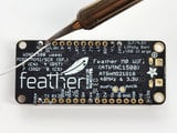
This is the Adafruit Feather HUZZAH ESP8266 - our take on an 'all-in-one' ESP8266 WiFi development board with built in USB and battery charging. Its an  ESP8266 WiFi module with all the extras you need, ready to rock! We have other boards in the Feather family, check'em out here.

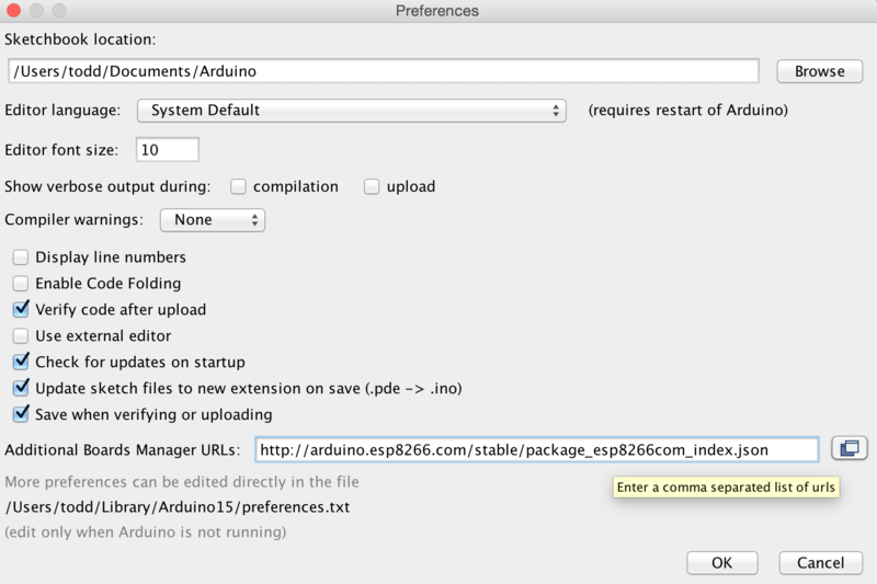
At the Feather HUZZAH's heart is an ESP8266 WiFi microcontroller clocked at 80 MHz and at 3.3V logic. This microcontroller contains a Tensilica chip core as well as a full WiFi stack. You can progam the microcontroller using the Arduino IDE for an easy-to-run Internet of Things core. We wired up a USB-Serial chip that can upload code at a blistering 921600 baud for fast development time. It also has auto-reset so no noodling with pins and reset button pressings.

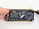
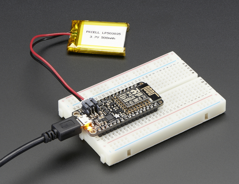
To make it easy to use for portable projects, we added a connector for any of our 3.7V Lithium polymer batteries and built in battery charging. You don't need a battery, it will run just fine straight from the micro USB connector. But, if you do have a battery, you can take it on the go, then plug in the USB to recharge. The Feather will automatically switch over to USB power when its available.

Here's some handy specs!

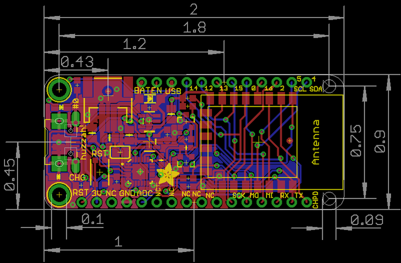
  • Measures 2.0" x 0.9" x 0.28" (51mm x 23mm x 8mm) without headers soldered in
  • Light as a (large?) feather - 6 grams
  • ESP8266 @ 80MHz or 160 MHz with 3.3V logic/power
  • 4MB of FLASH (32 MBit)
  • 3.3V regulator with 500mA peak current output
  • CP2104 USB-Serial converter onboard with 921600 max baudrate for uploading
  • Auto-reset support for getting into bootload mode before firmware upload
  • 9 GPIO pins - can also be used as I2C and SPI
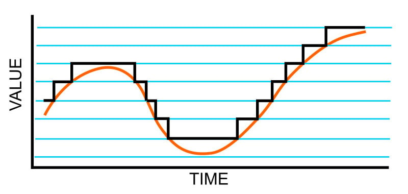
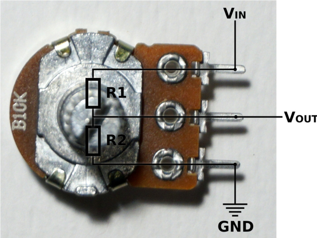
  • 1 x analog inputs 1.0V max
  • Built in 100mA lipoly charger with charging status indicator LED
  • Pin #0 red LED for general purpose blinking. Pin #2 blue LED for bootloading debug & general purpose blinking
  • Power/enable pin
  • 4 mounting holes
  • Reset button

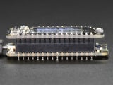
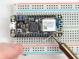
Comes fully assembled and tested, with a USB interface that lets you quickly use it with the Arduino IDE or NodeMCU Lua. (It comes preprogrammed with the Lua interpretter) We also toss in some header so you can solder it in and plug into a solderless breadboard. Lipoly battery and USB cable not included (but we do have lots of options in the shop if you'd like!)

Power Pins

  • GND - this is the common ground for all power and logic
  • BAT - this is the positive voltage to/from the JST jack for the optional Lipoly battery
  • USB - this is the positive voltage to/from the micro USB jack if connected
  • EN - this is the 3.3V regulator's enable pin. It's pulled up, so connect to ground to disable the 3.3V regulator
  • 3V - this is the output from the 3.3V regulator, it can supply 500mA peak (try to keep your current draw under 250mA so you have plenty for the ESP8266's power requirements!)

Logic pins

This is the general purpose I/O pin set for the microcontroller. All logic is 3.3V

The ESP8266 runs on 3.3V power and logic, and unless otherwise specified, GPIO pins are not 5V safe! The analog pin is also 1.0V max!

Serial pins

RX and TX are the serial control and bootloading pins, and are how you will spend most of your time communicating with the ESP module

The TX pin is the output from the module and is 3.3V logic.

The RX pin is the input into the module and is 5V compliant (there is a level shifter on this pin)

These are connected through to the CP2104 USB-to-Serial converter so they should not be connected to or used unless you're super sure you want to because you will also be getting the USB traffic on these!

I2C & SPI pins

You can use the ESP8266 to control I2C and SPI devices, sensors, outputs, etc. While this is done by 'bitbanging', it works quite well and the ESP8266 is fast enough to match 'Arduino level' speeds.

In theory you can use any pins for I2C and SPI but to make it easier for people using existing Arduino code, libraries, sketches we set up the following:

  • I2C SDA = GPIO #4 (default)
  • I2C SCL = GPIO #5 (default)

If you want, you can connect to I2C devices using other 2 pins in the Arduino IDE, by calling Wire.pins(sda, scl) before any other Wire code is called (so, do this at the begining of setup() for example

Likewise, you can use SPI on any pins but if you end up using 'hardware SPI' you will want to use the following:

  • SPI SCK = GPIO #14 (default)
  • SPI MOSI = GPIO #13 (default)
  • SPI MISO = GPIO #12 (default)

GPIO pins

This breakout has 9 GPIO: #0, #2, #4, #5, #12, #13, #14, #15, #16 arranged at the top edge of the Feather PCB

All GPIO are 3.3V logic level in and out, and are not 5V compatible.  Read the full spec sheet to learn more about the GPIO pin limits, but be aware the maximum current drawn per pin is 12mA.

These pins are general purpose and can be used for any sort of input or output. Most also have the ability to turn on an internal pullup. Many have special functionality:

GPIO #0, which does not have an internal pullup, and is also connected a red LED. This pin is used by the ESP8266 to determine when to boot into the bootloader. If the pin is held low during power-up it will start bootloading! That said, you can always use it as an output, and blink the red LED - note the LED is reverse wired so setting the pin LOW will turn the LED on.

GPIO #2, is also used to detect boot-mode. It also is connected to the blue LED that is near the WiFi antenna. It has a pullup resistor connected to it, and you can use it as any output (like #0) and blink the blue LED.

GPIO #15, is also used to detect boot-mode. It has a pulldown resistor connected to it, make sure this pin isn't pulled high on startup. You can always just use it as an output

GPIO #16 can be used to wake up out of deep-sleep mode, you'll need to connect it to the RESET pin

Also note that GPIO #12/13/14 are the same as the SCK/MOSI/MISO 'SPI' pins!

Analog Pins

There is also a single analog input pin called A. This pin has a ~1.0V maximum voltage, so if you have an analog voltage you want to read that is higher, it will have to be divided down to 0 - 1.0V range

Other control pins

We have a few other pins for controlling the ESP8266

  • RST - this is the reset pin for the ESP8266, pulled high by default. When pulled down to ground momentarily it will reset the ESP8266 system. This pin is 3.3V logic only
  • EN (CH_PD) - This is the enable pin for the ESP8266, pulled high by default. When pulled down to ground momentarily it will reset the ESP8266 system. This pin is 3.3V logic only

NC Pins

The rest of the pins are labeled NC which means Not Connected - they are not connected to anything and are there as placeholders only, to maintain physical compatibility with the other boards in the Feather line!

We ship Feathers fully tested but without headers attached - this gives you the most flexibility on choosing how to use and configure your Feather

Header Options!

Before you go gung-ho on soldering, there's a few options to consider!

The first option is soldering in plain male headers, this lets you plug in the Feather into a solderless breadboard

Another option is to go with socket female headers. This won't let you plug the Feather into a breadboard but it will let you attach featherwings very easily

A few Feather boards require access to top-side components like buttons or connectors, making stacking impractical. Sometimes you can stack in the opposite order—FeatherWing underneath—or, if both Feather and Wing require top-side access, place the boards side-by-side with a FeatherWing Doubler or Tripler.

We also  have 'slim' versions of the female headers, that are a little shorter and give a more compact shape

Finally, there's the "Stacking Header" option. This one is sort of the best-of-both-worlds. You get the ability to plug into a solderless breadboard and plug a featherwing on top. But its a little bulky

Soldering in Plain Headers

Prepare the header strip:

Cut the strip to length if necessary. It will be easier to solder if you insert it into a breadboard - long pins down

Add the breakout board:

Place the breakout board over the pins so that the short pins poke through the breakout pads

And Solder!

Be sure to solder all pins for reliable electrical contact.

(For tips on soldering, be sure to check out our Guide to Excellent Soldering).

Solder the other strip as well.

You're done! Check your solder joints visually and continue onto the next steps

Soldering on Female Header

Tape In Place

For sockets you'll want to tape them in place so when you flip over the board they don't fall out

Flip & Tack Solder

After flipping over, solder one or two points on each strip, to 'tack' the header in place

And Solder!

Be sure to solder all pins for reliable electrical contact.

(For tips on soldering, be sure to check out our Guide to Excellent Soldering).

You're done! Check your solder joints visually and continue onto the next steps

Don't power the Huzzah ESP8266 with a CanaKit 5V power supply, these power supplies have been destroying the CP2104 chip.

Battery + USB Power

We wanted to make our Feather boards easy to power both when connected to a computer as well as via battery.

There's two ways to power a Feather:

  1. You can connect with a USB cable (just plug into the jack) and the Feather will regulate the 5V USB down to 3.3V.
  2. You can also connect a 4.2/3.7V Lithium Polymer (LiPo/LiPoly) or Lithium Ion (LiIon) battery to the JST jack. This will let the Feather run on a rechargeable battery.

When the USB power is powered, it will automatically switch over to USB for power, as well as start charging the battery (if attached). This happens 'hot-swap' style so you can always keep the LiPoly connected as a 'backup' power that will only get used when USB power is lost.

The JST connector polarity is matched to Adafruit LiPoly batteries. Using wrong polarity batteries can destroy your Feather. Many customers try to save money by purchasing Lipoly batteries from Amazon only to find that they plug them in and the Feather is destroyed!

The above shows the Micro USB jack (left), LiPoly JST jack (top left), as well as the 3.3V regulator and changeover diode (just to the right of the JST jack) and the LiPoly charging circuitry (right below the regulator).

There's also a CHG LED next to the USB jack, which will light up while the battery is charging. This LED might also flicker if the battery is not connected, it's normal.

The charge LED is automatically driven by the LiPoly charger circuit. It will try to detect a battery and is expecting one to be attached. If there isn't one it may flicker once in a while when you use power because it's trying to charge a (non-existent) battery. It's not harmful, and it's totally normal!

Power Supplies

You have a lot of power supply options here! We bring out the BAT pin, which is tied to the LiPoly JST connector, as well as USB which is the +5V from USB if connected. We also have the 3V pin which has the output from the 3.3V regulator. We use a 500mA peak regulator. While you can get 500mA from it, you can't do it continuously from 5V as it will overheat the regulator.

We use this to power the ESP8266 which can draw spikes of 250+mA (although its not continuous).

You should be able to budget about 250mA current available from the regulator, which will leave plenty for the WiFi module.

Measuring Battery

If you're running off of a battery, chances are you wanna know what the voltage is at! That way you can tell when the battery needs recharging. LiPoly batteries are 'maxed out' at 4.2V and stick around 3.7V for much of the battery life, then slowly sink down to 3.2V or so before the protection circuitry cuts it off. By measuring the voltage you can quickly tell when you're heading below 3.7V.

Since the ESP8266 does not have multiple ADC pins, we didn't want to 'sacrifice' one for LiPoly battery monitoring. However we do have a tutorial that mentions how to do it, using two resistors. You can check out the wiring diagram here (use the VBat pin to measure) and the code here.

ENable pin

If you'd like to turn off the 3.3V regulator, you can do that with the EN(able) pin. Simply tie this pin to Ground and it will disable the 3V regulator. The BAT and USB pins will still be powered.

Alternative Power Options

The two primary ways for powering a feather are a 3.7/4.2V LiPo battery plugged into the JST port or a USB power cable.

If you need other ways to power the Feather, here's what we recommend:

Here's what you cannot do:

  • Do not use alkaline or NiMH batteries and connect to the battery port - this will destroy the LiPoly charger and there's no way to disable the charger
  • Do not use 7.4V RC batteries on the battery port - this will destroy the board

The Feather is not designed for external power supplies - this is a design decision to make the board compact and low cost. It is not recommended, but technically possible:

  • Connect an external 3.3V power supply to the 3V and GND pins. Not recommended, this may cause unexpected behavior and the EN pin will no longer work. Also this doesn't provide power on BAT or USB and some Feathers/Wings use those pins for high current usages. You may end up damaging your Feather.
  • Connect an external 5V power supply to the USB and GND pins. Not recommended, this may cause unexpected behavior when plugging in the USB port because you will be back-powering the USB port, which could confuse or damage your computer.

Each Feather HUZZAH ESP8266 breakout comes pre-programmed with NodeMCU's Lua interpreter. As of this writing, we ship with NodeMCU 0.9.5 build 20150318  powered by Lua 5.1.4 but it may be more recent

Lua is still a work in progress, so we strongly recommend visiting NodeMCU and updating your Lua version to the very latest as they have the ability to make you the latest continuous build. Then follow their guide on how to update Lua!

The Lua interpreter runs on the ESP8266 and you can type in commands and read out the results over serial. In order to upload code to the ESP8266 and use the serial console, connect any data-capable micro USB cable to the Feather HUZZAH and the other side to your computer's USB port. Install the required CP2104 USB driver to have the COM/Serial port appear properly

Don't forget to visit esp8266.com for the latest and greatest in ESP8266 news, software and gossip!

Don't forget to install the USB driver for the CP2104 USB-to-Serial chip!

Open up serial console

Next up, on your computer, use a serial console program such as CoolTerm (Mac) or Putty (Windows) or screen (linux). Teraterm seems to dislike the initial 74400bps data stream from the ESP8266 so you can try it but you'll possibly need to reset the terminal software.

  • Connect up to the COM or Serial port used by your cable, at 9600 Baud
  • Make sure you have turned off any hardware handshake or flow control
  • Putty isn't good with pasting code in, so you may not be able to copy-n-paste!
  •  Also make sure you have line endings set to CRLF "\r\n"

Use any serial console program you like, we just happen to be used to Putty!

Once the terminal software is connected, click the Reset button on the Feather HUZZAH ESP8266 board to reset it and have it print out the welcome message:

If you don't get this message, first check that the red/blue leds flickered when you press the reset button. If they didnt, make sure you've got the right baud rate selected in the software (9600)

Hello world!

Ok we can now turn on an LED. There is a red LED on each board, connected to GPIO #0

NodeMCU Lua's pinouts are not the same as the Arduino/gcc pinouts. We print the Arduino pinouts on the board so watch out!
The Lua documentation for the ESP8266 has GPIO #4 and #5 swapped so if #4/#5 aren't working for you, try swapping!

Pin Notes

PCB/Arduino

NodeMCU/Lua

No pullups!

0

3

2

4

CHPD (Note, don't use this pin or set it to be an output!)

3

9

4

1

5

2

9

11

10

12

12

6

13

7

14

5

15

8

16

0

So to set the pin #0 LED on and off (which would be pin #3 in Lua) first make it an output:

gpio.mode(3, gpio.OUTPUT)

Turn the LED on with:

gpio.write(3, gpio.LOW)

And off with:

gpio.write(3, gpio.HIGH)

You can make this a little more automated by running a longer script.

For longer text, pasting can be difficult as the lua interpreter needs a little delay time between characters and also require CR-LF settings. For that reason you may want to paste each line and then hit return manually.

while 1 do
  gpio.write(3, gpio.HIGH)
  tmr.delay(1000000)   -- wait 1,000,000 us = 1 second
  gpio.write(3, gpio.LOW)
  tmr.delay(1000000)   -- wait 1,000,000 us = 1 second
end

The LED will now be blinking on and off.

Note that since its in a loop, its not possible to get it to stop via the interpreter. To stop it, click the Reset button again!

This code halts the processor during the tmr.delay, a smarter way to blink an LED is to use the timer capability to set off the LED control (code from here)

-- Pin definition 
local pin = 3
local status = gpio.LOW
local duration = 1000    -- 1 second duration for timer

-- Initialising pin
gpio.mode(pin, gpio.OUTPUT)
gpio.write(pin, status)

-- Create an interval
tmr.alarm(0, duration, 1, function ()
    if status == gpio.LOW then
        status = gpio.HIGH
    else
        status = gpio.LOW
    end

    gpio.write(pin, status)
end)

Scanning & Connecting to WiFi

We'll continue with a quick demo of scanning for WiFi and connecting.

Once you're back at the Lua prompt, set the ESP8266 into WiFi Client mode with

wifi.setmode(wifi.STATION)

Then you can run the scanner and have it print out the available AP's

-- print ap list
function listap(t)
      for k,v in pairs(t) do
        print(k.." : "..v)
      end
end
wifi.sta.getap(listap)

or for more detail...

-- print ap list
function listap(t)
      for ssid,v in pairs(t) do
        authmode, rssi, bssid, channel = string.match(v, "(%d),(-?%d+),(%x%x:%x%x:%x%x:%x%x:%x%x:%x%x),(%d+)")
        print(ssid,authmode,rssi,bssid,channel)
      end
end
      
wifi.sta.getap(listap)

We can connect to the access point with wifi.sta.config and wifi.sta.connect - it will take a second or two to complete the connection, you can query the module to ask the status with wifi.sta.status() - when you get a 5 it means the connection is completed and DHCP successful

wifi.sta.config("accesspointname","yourpassword")
wifi.sta.connect()
tmr.delay(1000000)   -- wait 1,000,000 us = 1 second
print(wifi.sta.status())
print(wifi.sta.getip())

WebClient example

Once you're got the IP address you can connect to adafruit, for example, and read a webpage and print it out:

sk=net.createConnection(net.TCP, 0)
sk:on("receive", function(sck, c) print(c) end )
sk:connect(80,"207.58.139.247")
sk:send("GET /testwifi/index.html HTTP/1.1\r\nHost: www.adafruit.com\r\nConnection: keep-alive\r\nAccept: */*\r\n\r\n")

You can also have the module do DNS for you, just give it the hostname instead of IP address:

sk=net.createConnection(net.TCP, 0)
sk:on("receive", function(sck, c) print(c) end )
sk:connect(80,"www.adafruit.com")
sk:send("GET /testwifi/index.html HTTP/1.1\r\nHost: www.adafruit.com\r\nConnection: keep-alive\r\nAccept: */*\r\n\r\n")

This is just a light overview of testing out your HUZZAH ESP breakout! For much more, check out NodeMCU's documentation page https://nodemcu.readthedocs.io/ for the details on what functions are available to you, as well as  http://www.lua.org to learn more about the Lua scripting language

While the Feather HUZZAH ESP8266 comes pre-programmed with NodeMCU's Lua interpretter, you don't have to use it! Instead, you can use the Arduino IDE which may be more familar. This will write directly to the firmware, erasing the NodeMCU firmware, so if you want to go back to Lua, use the flasher to re-install it

Don't forget to visit esp8266.com for the latest and greatest in ESP8266 news, software and gossip!

In order to upload code to the ESP8266 and use the serial console, connect any data-capable micro USB cable to the Feather HUZZAH and the other side to your computer's USB port.

Don't forget you will also need to install the SiLabs CP2104 Driver:

On Mac OS 10.13 and higher, in addition to installing, you will have to give the CP2104 kernel driver permission to load. You can find out if you need to give additional permission by visiting your Security & Privacy settings system preferences screen after installing and looking for the message that says, 'System software from developer "SiLabs" was blocked from loading', like in the picture below.

To allow the driver to load, click the lock icon, enter your password, and click "Allow" next to the warning message. After that, you may have to restart your computer before following the steps below and connecting to your Huzzah in the Arduino app.

If you are using Mac OS 10.12.6 (Sierra) and you cannot upload with the latest Mac OS VCP driver, please try the legacy v4 driver below. Note you will need to uninstall the v5 driver using uninstall.sh (in the driver package)

Install the Arduino IDE 1.6.8 or greater

Download Arduino IDE from Arduino.cc (1.6.8 or greater) from Arduino.cc

The latest is usually the best

Install the ESP8266 Board Package

Enter http://arduino.esp8266.com/stable/package_esp8266com_index.json into Additional Board Manager URLs field in the Arduino v1.6.4+ preferences.

 Next, use the Board manager to install the ESP8266 package.

If you want to use this board with Adafruit IO Arduino - make sure you're on version 2.5.1 or ABOVE.

After the install process, you should see that esp8266 package is marked INSTALLED. Close the Boards Manager window once the install process has completed.

Setup ESP8266 Support

When you've restarted, select Adafruit Feather HUZZAH ESP8266  from the Tools->Board dropdown

80 MHz as the CPU frequency

You can keep the Flash Sizeat "4M (3M SPIFFS)

For Upload Speed, select 115200 baud (You can also try faster baud rates, we were able to upload at a blistering 921600 baud but sometimes it fails & you have to retry)

The matching COM port for your FTDI or USB-Serial cable

On a mac, you should look for the "SLAB_USBtoUART" port

Blink Test

We'll begin with the simple blink test

Enter this into the sketch window (and save since you'll have to)

void setup() {
  pinMode(0, OUTPUT);
}

void loop() {
  digitalWrite(0, HIGH);
  delay(500);
  digitalWrite(0, LOW);
  delay(500);
}

Now you can simply upload! The Feather HUZZAH has built in auto-reset that puts it into bootloading mode automagically

The sketch will start immediately - you'll see the LED blinking. Hooray!

Connecting via WiFi

OK once you've got the LED blinking, lets go straight to the fun part, connecting to a webserver. Create a new sketch with this code:

/*
 *  Simple HTTP get webclient test
 */

#include <ESP8266WiFi.h>

const char* ssid     = "yourssid";
const char* password = "yourpassword";

const char* host = "wifitest.adafruit.com";

void setup() {
  Serial.begin(115200);
  delay(100);

  // We start by connecting to a WiFi network

  Serial.println();
  Serial.println();
  Serial.print("Connecting to ");
  Serial.println(ssid);
  
  WiFi.begin(ssid, password);
  
  while (WiFi.status() != WL_CONNECTED) {
    delay(500);
    Serial.print(".");
  }

  Serial.println("");
  Serial.println("WiFi connected");  
  Serial.println("IP address: ");
  Serial.println(WiFi.localIP());
}

int value = 0;

void loop() {
  delay(5000);
  ++value;

  Serial.print("connecting to ");
  Serial.println(host);
  
  // Use WiFiClient class to create TCP connections
  WiFiClient client;
  const int httpPort = 80;
  if (!client.connect(host, httpPort)) {
    Serial.println("connection failed");
    return;
  }
  
  // We now create a URI for the request
  String url = "/testwifi/index.html";
  Serial.print("Requesting URL: ");
  Serial.println(url);
  
  // This will send the request to the server
  client.print(String("GET ") + url + " HTTP/1.1\r\n" +
               "Host: " + host + "\r\n" + 
               "Connection: close\r\n\r\n");
  delay(500);
  
  // Read all the lines of the reply from server and print them to Serial
  while(client.available()){
    String line = client.readStringUntil('\r');
    Serial.print(line);
  }
  
  Serial.println();
  Serial.println("closing connection");
}

Dont forget to update

const char* ssid     = "yourssid";
const char* password = "yourpassword";

to your access point and password, then upload the same way: get into bootload mode, then upload code via IDE

Open up the IDE serial console at 115200 baud to see the connection and webpage printout!

That's it, pretty easy!

This page was just to get you started and test out your module. For more information, check out the ESP8266 port github repository for much more up-to-date documentation!

The WipperSnapper firmware and ecosystem are in BETA and are actively being developed to add functionality, more boards, more sensors, and fix bugs. We encourage you to try out WipperSnapper with the understanding that it is not final release software and is still in development. If you encounter any bugs, glitches, or difficulties during the beta period, or with this guide, please contact us via http://io.adafruit.com/support

What is WipperSnapper

WipperSnapper is a firmware designed to turn any WiFi-capable board into an Internet-of-Things device without programming a single line of code. WipperSnapper connects to Adafruit IO, a web platform designed (by Adafruit!) to display, respond, and interact with your project's data.

Simply load the WipperSnapper firmware onto your board, add credentials, and plug it into power. Your board will automatically register itself with your Adafruit IO account.

From there, you can add components to your board such as buttons, switches, potentiometers, sensors, and more! Components are dynamically added to hardware, so you can immediately start interacting, logging, and streaming the data your projects produce without writing code.

Sign up for Adafruit.io

You will need an Adafruit IO account to use WipperSnapper on your board. If you do not already have one, head over to io.adafruit.com to create a free account.

Add a New Device to Adafruit IO

Log into your Adafruit IO account. Click the New Device button at the top of the page.

After clicking New Device, you should be on the board selector page. This page displays every board that is compatible with the WipperSnapper firmware.

In the board selector page's search bar, search for the Feather HUZZAH ESP8266. Once you've located the board you'd like to install WipperSnapper on, click the Choose Board button to bring you to the self-guided installation wizard.

Follow the step-by-step instructions on the page to install Wippersnapper on your device and connect it to Adafruit IO.

If the installation was successful, a popover should appear displaying that your board has successfully been detected by Adafruit IO.

Give your board a name and click "Continue to Device Page".

You should be brought to your board's device page.

Next, Visit this guide's WipperSnapper Essentials pages to learn how to interact with your board using Adafruit IO.

Feedback

Adafruit.io WipperSnapper is in beta and you can help improve it!

If you have  suggestions or general feedback about the installation process - visit https://io.adafruit.com/support, click "Contact Adafruit IO Support" and select "I have feedback or suggestions for the WipperSnapper Beta".

Troubleshooting

If you encountered an issue during installation, please try the steps below first.

If you're still unable to resolve the issue, or if your issue is not listed below, get in touch with us directly at https://io.adafruit.com/support. Make sure to click  "Contact Adafruit IO Support" and select "There is an issue with WipperSnapper. Something is broken!"

I don't see my board on Adafruit IO, it is stuck connecting to WiFi

First, make sure that you selected the correct board on the board selector.

Next, please make sure that you entered your WiFi credentials properly, there are no spaces/special characters in either your network name (SSID) or password, and that you are connected to a 2.4GHz wireless network.

If you're still unable to connect your board to WiFi, please make a new post on the WipperSnapper technical support forum with the error you're experiencing, the LED colors which are blinking, and the board you're using.

I don't see my board on Adafruit IO, it is stuck "Registering with Adafruit IO"

Try hard-resetting your board by unplugging it from USB power and plugging it back in.

If the error is still occurring, please make a new post on the WipperSnapper technical support forum with information about what you're experiencing, the LED colors which are blinking (if applicable), and the board you're using.

"Uninstalling" WipperSnapper 

WipperSnapper firmware is an application that is loaded onto your board. There is nothing to "uninstall". However, you may want to "move" your board from running WipperSnapper to running Arduino or CircuitPython. You also may need to restore your board to the state it was shipped to you from the Adafruit factory. 

Moving from WipperSnapper to CircuitPython

Follow the steps on the Installing CircuitPython page to install CircuitPython on your board running WipperSnapper.

  • If you are unable to double-tap the RST button to enter the UF2 bootloader, follow the "Factory Resetting a WipperSnapper Board" instructions below.

Uploading this sketch will overwrite WipperSnapper. If you want to re-install WipperSnapper, follow the instructions at the top of this page.

Moving from WipperSnapper to Arduino

If you want to use your board with Arduino, you will use the Arduino IDE to load any sketch onto your board.

First, follow the page below to set up your Arduino IDE environment for use with your board.

Then, follow the page below to upload the "Arduino Blink" sketch to your board.

Uploading this sketch will overwrite WipperSnapper. If you want to re-install WipperSnapper, follow the instructions at the top of this page.

Factory Resetting a WipperSnapper Board

Sometimes, hardware gets into a state that requires it to be "restored" to the original state it shipped in. If you'd like to get your board back to its original factory state, follow the guide below.

Note: This board does not have a factory reset firmware file. You should upload the Arduino blink sketch by following the instructions above.

You've installed WipperSnapper firmware on your board and connected it to Adafruit IO. Next, let's learn how to use Adafruit IO!

The Adafruit IO supports a large number of components. Components are physical parts such as buttons, switches, sensors, servos, LEDs, RGB LEDs, and more. 

The following pages will get you up and running with WipperSnapper as you interact with your board's LED, read the value of a push button, send the value of an I2C sensor to the internet, and wirelessly control colorful LEDs.

Parts

The following parts are required to complete the WipperSnapper essentials pages for this board:

Video of a white hand turning the knob on a STEMMA Wired Potentiometer Breakout Board connect to a breadboard. Color changes when the knob is twisted.
For the easiest way possible to measure twists, turn to this STEMMA potentiometer breakout (ha!). This plug-n-play pot comes with a JST-PH 2mm connector and a matching  
Top view of temperature sensor breakout above an OLED display FeatherWing. The OLED display reads "MCP9808 Temp: 24.19ºC"
The MCP9808 digital temperature sensor is one of the more accurate/precise we've ever seen, with a typical accuracy of ±0.25°C over the sensor's -40°C to...
Angled shot of 10 12mm square tactile switch buttons.
Medium-sized clicky momentary switches are standard input "buttons" on electronic projects. These work best in a PCB but
Angled shot of half-size solderless breadboard with red and black power lines.
This is a cute, half-size breadboard with 400 tie points, good for small projects. It's 3.25" x 2.2" / 8.3cm x 5.5cm with a standard double-strip in the...
Bundle of multi-colored multi-length wire jumpers
75 flexible stranded core wires with stiff ends molded on in red, orange, yellow, green, blue, brown, black and white. These are a major improvement over the "box of bent...
Top view of JST SH 4-pin to Premium Male Headers Cable next to US quarter for scale.
This 4-wire cable is a little over 150mm / 6" long and fitted with JST-SH female 4-pin connectors on one end and premium Dupont male headers on the other. Compared with the...

This demo shows controlling an LED from Adafruit IO. The same kind of control can be used for relays, lights, motors, or solenoids.

One of the first programs you typically write to get used to embedded programming is a sketch that repeatably blinks an LED. IoT projects are wireless, so after completing this section, you'll be able to turn on (or off) the LED built into your board from anywhere in the world.

Where is the LED on my board?

The Adafruit Feather HUZZAH ESP8266 has a LED (highlighted in red and labeled on the silkscreen as #0) above the Micro-USB port.

Create a LED Component on Adafruit IO

On the device page, click the New Component (or "+") button to open the component picker.

Search for the component name by entering LED into the text box on the component picker, the list of components should update as soon as you stop typing.

Filtering and searching for components

Since WipperSnapper supports such a large number of components, there is keyword filtering. Try searching for various keywords, like:

  • component names: aht20servobuzzerbutton, led, etc
  • sensor types: lighttemperaturepressurehumidity, etc
  • interface: i2cuartds18x20pin, etc (also I2C addresses e.g. 0x44)
  • vendor: AdafruitASAIRInfineonBosch, Honeywell, Sensirion, etc

There are also product and documentation links to every component. Follow the links beneath the component descriptions to be taken to the appropriate product page or Learn Guide

Select the LED from the list of components.

On the Create LED Component form, the board's LED pin is pre-selected. 

Click Create Component.

Behind the scenes, Adafruit IO sends send a command to your board running WipperSnapper telling it to configure "LED Pin" as a digital output.

Your board's page on Adafruit IO shows a new LED component.

Usage

On the board page, toggle the LED component by clicking the toggle switch. This should turn your board's built-in LED on or off.

In this demo, we show reading the state of a push-button from WipperSnapper. But the same kind of control can be used for reading switches, break beam sensors, and other digital sensors.

You can configure a board running WipperSnapper to read data from standard input buttons, switches, or digital sensors, and send the value to Adafruit IO.

From Adafruit IO, you will configure one of the pushbuttons on your board as a push button component. Then, when the button is pressed (or released), a value will be published to Adafruit IO.

Parts

The following parts are required to complete this page.

Angled shot of 10 12mm square tactile switch buttons.
Medium-sized clicky momentary switches are standard input "buttons" on electronic projects. These work best in a PCB but
$2.50
In Stock
Angled shot of half-size solderless breadboard with red and black power lines.
This is a cute, half-size breadboard with 400 tie points, good for small projects. It's 3.25" x 2.2" / 8.3cm x 5.5cm with a standard double-strip in the...
$4.95
In Stock
Bundle of multi-colored multi-length wire jumpers
75 flexible stranded core wires with stiff ends molded on in red, orange, yellow, green, blue, brown, black and white. These are a major improvement over the "box of bent...
$4.95
In Stock

Wiring

  • Feather GND to Push Button
  • Feather GPIO 13 to Push Button

Note - we are not using a resistor part! We will be configuring the Feather ESP32 to use its internal resistor instead.

Create a Push-button Component on Adafruit IO

On the device page, click the New Component (or "+") button to open the component picker.

Search for the component name by entering push into the text box on the component picker, the list of components should update as soon as you stop typing.

Filtering and searching for components

WipperSnapper supports such a large number of components we added filtering!
Try searching for various keywords, like:

  • component names: aht20servobuzzerbutton, relay, etc
  • sensor types: lighttemperaturepressurehumidity, etc
  • interface: i2cuartds18x20pin, etc (also I2C addresses e.g. 0x44)
  • vendor: AdafruitASAIRInfineonBosch, Honeywell, Sensirion, etc

We’ve also added product and documentation links to every component, follow the links beneath the component descriptions to be taken to the appropriate product page or Learn-Guide.

Select the Push Button from the list of results to go to the component configuration page.

There will be a back button if you select the wrong component, and you can use the Edit component icon (⚙️) on the device page to update the component configuration in the future.

The "Create Push Button Component" form presents you with options for configuring the push button.

Start by selecting the board's pin connected to the push button.

The Return Interval dictates how frequently the value of the push-button will be sent from the board to Adafruit IO.

For this example, you will configure the push button value to be only sent when the value changes (i.e.: when it's either pressed or depressed).

Check the Specify Pin Pull Direction checkbox.

Select Pull Up to turn on the internal pull-up resistor.

Make sure the form settings look like the following screenshot. Then, click Create Component.

Adafruit IO sends a command to your WipperSnapper board, telling it to configure the GPIO pin you selected to behave as a digital input pin and to enable it to pull up the internal resistor.

Your board page should also show the new push-button component.

Push the button on your board to change the value of the push-button component on Adafruit IO.

Your microcontroller board has both digital and analog signal capabilities. Some pins are analog, some are digital, and some are capable of both. Check the Pinouts page in this guide for details about your board.

Analog signals are different from digital signals in that they can be any voltage and can vary continuously and smoothly between voltages. An analog signal is like a dimmer switch on a light, whereas a digital signal is like a simple on/off switch. 

Digital signals only can ever have two states, they are either are on (high logic level voltage like 3.3V) or off (low logic level voltage like 0V / ground).

By contrast, analog signals can be any voltage in-between on and off, such as 1.8V or 0.001V or 2.98V and so on.

Analog signals are continuous values which means they can be an infinite number of different voltages. Think of analog signals like a floating point or fractional number, they can smoothly transiting to any in-between value like 1.8V, 1.81V, 1.801V, 1.8001V, 1.80001V and so forth to infinity.

Many devices use analog signals, in particular sensors typically output an analog signal or voltage that varies based on something being sensed like light, heat, humidity, etc.

Analog to Digital Converter (ADC)

An analog-to-digital-converter, or ADC, is the key to reading analog signals and voltages with a microcontroller. An ADC is a device that reads the voltage of an analog signal and converts it into a digital, or numeric, value. The microcontroller can’t read analog signals directly, so the analog signal is first converted into a numeric value by the ADC. 

The black line below shows a digital signal over time, and the red line shows the converted analog signal over the same amount of time.

Once that analog signal has been converted by the ADC, the microcontroller can use those digital values any way you like!

Potentiometers

A potentiometer is a small variable resistor that you can twist a knob or shaft to change its resistance. It has three pins. By twisting the knob on the potentiometer you can change the resistance of the middle pin (called the wiper) to be anywhere within the range of resistance of the potentiometer.

By wiring the potentiometer to your board in a special way (called a voltage divider) you can turn the change in resistance into a change in voltage that your board’s analog to digital converter can read.

To wire up a potentiometer as a voltage divider:

  • Connect one outside pin to ground
  • Connect the other outside pin to voltage in (e.g. 3.3V)
  • Connect the middle pin to an analog pin (e.g. A0)

Hardware

In addition to your microcontroller board, you will need the following hardware to follow along with this example.

Potentiometer

Video of a white hand turning the knob on a STEMMA Wired Potentiometer Breakout Board connect to a breadboard. Color changes when the knob is twisted.
For the easiest way possible to measure twists, turn to this STEMMA potentiometer breakout (ha!). This plug-n-play pot comes with a JST-PH 2mm connector and a matching  
$3.95
In Stock

Wire Up the Potentiometer

Connect the potentiometer to your board as follows.

  • Feather 3.3V to potentiometer left pin
  • Feather ADC to potentiometer middle pin
  • Feather GND to potentiometer right pin

Create a Potentiometer Component on Adafruit IO

On the device page, click the New Component (or "+") button to open the component picker.

Search for the component name by entering potentiometer into the text box on the component picker, the list of components should update as soon as you stop typing.

Filtering and searching for components

Since WipperSnapper supports such a large number of components, there is keyword filtering. Try searching for various keywords, like:

  • component names: aht20servobuzzerbutton, potentiometer, etc
  • sensor types: lighttemperaturepressurehumidity, etc
  • interface: i2cuartds18x20pin, etc (also I2C addresses e.g. 0x44)
  • vendor: AdafruitASAIRInfineonBosch, Honeywell, Sensirion, etc

There are also added product and documentation links for every component, follow the links beneath the component descriptions to be taken to the appropriate product page or Learn Guide.

Select the Potentiometer from the list of results to go to the component configuration page.

There will be a back button if you select the wrong component, and you can use the Edit component icon (⚙️) on the device page to update the component configuration in the future.

On the Create Potentiometer Component form:

  • Set Potentiometer Pin to A0
  • Select "On Change" as the Return Interval
  • Select Raw Analog Value as the Return Type

Then, click Create Component

The potentiometer component appears on your board page! Next, learning to read values from it.

Read Analog Pin Values

Rotate the potentiometer to see the value change.

What do these values mean?

WipperSnapper reports ADC "raw values" as 16-bit unsigned integer values. Your potentiometer will read between 0 (twisting the pot to the leftmost position) and 65535 (twisting the pot to the rightmost position). 

Read Analog Pin Voltage Values

You can update the potentiometer component (or any analog pin component in WipperSnapper) to report values in Volts. To do this, on the right-hand side of the potentiometer component, click the cog button.

Under Return Type, click Voltage.

Click Update Component to send the updated component settings to your board running WipperSnapper.

Now, twist the potentiometer to see the value reported to Adafruit IO in Volts!

While this page uses the "MCP9808 High Accuracy I2C Temperature Sensor Breakout", the process for adding an I2C sensor to your board running WipperSnapper is similar for all I2C sensors.

Inter-Integrated Circuit, aka I2C, is a two-wire protocol for connecting sensors and "devices" to a microcontroller. A large number of sensors, including the ones sold by Adafruit, use I2C to communicate. 

Typically, using I2C with a microcontroller involves programming. Adafruit IO and WipperSnapper let you configure a microcontroller to read data from an I2C sensor and publish that data to the internet without writing code.

The WipperSnapper firmware supports a number of I2C sensors, viewable in list format here.

On this page, you'll learn how to wire up an I2C sensor to your board. Then, you'll create a new component on Adafruit IO for your I2C sensor and send the sensor values to Adafruit IO. Finally, you'll learn how to locate, interpret, and download the data produced by your sensors.

Parts

You will need the following parts to complete this page:

Top view of temperature sensor breakout above an OLED display FeatherWing. The OLED display reads "MCP9808 Temp: 24.19ºC"
The MCP9808 digital temperature sensor is one of the more accurate/precise we've ever seen, with a typical accuracy of ±0.25°C over the sensor's -40°C to...
$4.95
In Stock
Top view of JST SH 4-pin to Premium Male Headers Cable next to US quarter for scale.
This 4-wire cable is a little over 150mm / 6" long and fitted with JST-SH female 4-pin connectors on one end and premium Dupont male headers on the other. Compared with the...
Out of Stock

Wiring

If you're using a breadboard or a "STEMMA QT / Qwiic JST SH 4-pin to Premium Male Headers Cable":

  • Board power to MCP9808 VIN
  • Board ground to MCP9808 GND
  • Board SCL to MCP9808 SCL
  • Board SDA to MCP9808 SDA

Add an MCP9808 Component

On the device page, click the New Component (or "+") button to open the component picker.

Search for the component name by entering MCP9808 into the text box on the component picker, the list of components should update as soon as you stop typing.

Filtering and searching for components

Since WipperSnapper supports such a large number of components, there is keyword filtering. Try searching for various keywords, like:

  • component names: aht20servobuzzerbutton, potentiometer, etc
  • sensor types: lighttemperaturepressurehumidity, etc
  • interface: i2cuartds18x20pin, etc (also I2C addresses e.g. 0x44)
  • vendor: AdafruitASAIRInfineonBosch, Honeywell, Sensirion, etc

There are added product and documentation links for every component, follow the links beneath the component descriptions to be taken to the appropriate product page or Learn Guide.

Select the MCP9808 from the list of results to go to the component configuration page.

There will be a back button if you select the wrong component, and you can use the Edit component icon (⚙️) on the device page to update the component configuration in the future.

On the component configuration page, the MCP9808's I2C sensor address should be listed along with the sensor's settings.

The MCP9808 sensor can measure ambient temperature. This page has individual options for reading the ambient temperature, in either Celsius or Fahrenheit. You may select the readings which are appropriate to your application and region.

The Send Every option is specific to each sensor measurement. This option will tell the board how often it should read from the sensor and send the data to Adafruit IO. Measurements can range from every 30 seconds to every 24 hours.

For this example, set the Send Every interval for both seconds to Every 30 seconds. Click Create Component.

The board page should now show the MCP9808 component you created. After the interval you configured elapses, the WipperSnapper firmware running on your board automatically reads values from the sensor and sends them to Adafruit IO.

Read I2C Sensor Values

Now to look behind the scenes at a powerful element of using Adafruit IO and WipperSnapper. When a new component is created on Adafruit IO, an Adafruit IO Feed is also created. This Feed holds your sensor component values for long-term storage (30 days of storage for Adafruit IO Free and 60 days for Adafruit IO Plus plans).

Aside from holding the values read by a sensor, the component's feed also holds metadata about the data pushed to Adafruit IO. This includes settings for whether the data is public or private, what license the stored sensor data falls under, and a general description of the data.

Next, to look at the sensor temperature feed. To navigate to a component's feed, click on the chart icon in the upper-right-hand corner of the component.

On the component's feed page, you'll each data point read by your sensor and when they were reported to Adafruit IO.

Doing more with your sensor's Adafruit IO Feed

This only scratches the surface of what Adafruit IO Feeds can accomplish for your IoT projects. For a complete overview of Adafruit IO Feeds, including tasks like downloading feed data, sharing a feed, removing erroneous data points from a feed, and more, head over to the "Adafruit IO Basics: Feed" learning guide.

When I connect stuff to some of the pins, the Huzzah stops working. Whats up with that?

The ESP8266 uses some of the pins as 'boot mode' pins so on boot they must be set to certain values:

  • CH_PD (EN) should be always pulled high (it will disable the entire module if low)
  • RST should be always pulled high (it will disable the entire module if low)
  • GPIO 0 sets whether the bootloader is active, it must be pulled HIGH during power up/reset for the user program to run. If it's pulled LOW, it will activate the bootloader. The built-in red LED on #0 pulls it up
  • GPIO 2 must be pulled high on power up/reset.
  • GPIO 15 must be pulled low on power up/reset.
My Huzzah board keeps crashing and resetting, whats up with that?

The most common reason for crashes is power failure. Make sure you're powering the Huzzah with a good ~5V power supply, and if you're using a USB-Serial cable, that it's plugged into the mainboard of your computer or through a powered hub!

I can't seem to find the Serial port on my computer for the Feather HUZZAH?

Don't forget to install the CP2104 VCP drivers for your computer, they are required!

I still can't seem to find the Serial port on my computer for the Feather Huzzah!

Many cheap electronics come with charge-only USB cables, which cause headaches later. Make sure you are using a proper data/sync USB cable. If you find a cable that is charge-only (not data/sync also) throw it out so you don't have the same problem again.

So, I’m getting a 'no such file' error compiling for ESP8266 on my Mac

If your error message looks like this:

fork/exec /Users/xxxxxxx/Library/Arduino15/packages/esp8266/tools/xtensa-lx106-elf-gcc/1.20.0-26-gb404fb9-2/bin/xtensa-lx106-elf-g++: no such file or directory
Error compiling.

To fix this problem, do this:

  1. Open the Boards Manager in the Arduino IDE
  2. Uninstall the ESP8266 support
  3. go to your ~LIbrary folder (in the Finder, select "Go::Go to folder:, and enter ~Library ). Find the folder Arduino15.
  4. In the Arduino15 folder, go into packages, and delete the folder esp8266
  5. Go back to the Arduino IDE, and install ESP8266 board support.
  6. Now go back to the Finder, and check that you have the xtensa-lx106-elf-g++ file in the path Arduino15/packages/esp8266/tools/xtensa-lx106-elf-gcc/1.20.0-26-gb404fb9-2/bin/xtensa-lx106-elf-g++
  7. That's it!
Whenever I start or reset the ESP8226 there's a bunch of "gibberish" on the Serial console

This is the ROM debug messages, it's transmitted at 74880 baud so you rarely see it in proper 'ascii output' - instead usually it gets corrupted into a bunch of strange characters.

I'm having difficulties uploading to the HUZZAH with the Arduino IDE

Make sure you're using a good quality USB/Serial cable. Install the official drivers for that cable too! We've also noticed that PL2303-based cables don't work on Macs for some reason. FTDI or CP210x based chipsets work best

I tried that, but I'm still having difficulties uploading with the Arduino IDE

Sometimes, it helps to switch the board type to "Generic ESP8266 Module".  Set the Reset Method to "nodemcu"

See this forum post

I'm stuck in bootloader mode and can't upload

You say your led is stuck on dim and you get an error trying to upload? And you're sure your serial cable is connected and working correctly? Well, here's a potential fix: Connect the GPIO0 pin to GND through a 220 ohm resistor. Leave it connected while you upload.  You may have to try it a couple of times, but it should eventually upload and get the HUZZAH unstuck from bootload mode! You can then remove the resistor connection, and your HUZZAH will be happy ever after!

(Note: you may also have to tie RST and EN (CH_PD) together to get this to work.  Remove the connection once you have the module programmed).

Thanks to forum user misslevania for the tip!

I can't get Lua to respond to my commands

Make sure your terminal software is sending correct line endings! The default PuTTY settings may be wrong when trying to talk to Lua on an ESP8266. Lua expects CRLF "\r\n" line endings, and apparently PuTTY defaults to just LF "\n"!

This guide was first published on Nov 25, 2015. It was last updated on Mar 26, 2024.