Your microcontroller board has both digital and analog signal capabilities. Some pins are analog, some are digital, and some are capable of both. Check the Pinouts page in this guide for details about your board.
Analog signals are different from digital signals in that they can be any voltage and can vary continuously and smoothly between voltages. An analog signal is like a dimmer switch on a light, whereas a digital signal is like a simple on/off switch.
Digital signals only can ever have two states, they are either are on (high logic level voltage like 3.3V) or off (low logic level voltage like 0V / ground).
By contrast, analog signals can be any voltage in-between on and off, such as 1.8V or 0.001V or 2.98V and so on.
Analog signals are continuous values which means they can be an infinite number of different voltages. Think of analog signals like a floating point or fractional number, they can smoothly transiting to any in-between value like 1.8V, 1.81V, 1.801V, 1.8001V, 1.80001V and so forth to infinity.
Many devices use analog signals, in particular sensors typically output an analog signal or voltage that varies based on something being sensed like light, heat, humidity, etc.
Analog to Digital Converter (ADC)
An analog-to-digital-converter, or ADC, is the key to reading analog signals and voltages with a microcontroller. An ADC is a device that reads the voltage of an analog signal and converts it into a digital, or numeric, value. The microcontroller can’t read analog signals directly, so the analog signal is first converted into a numeric value by the ADC.
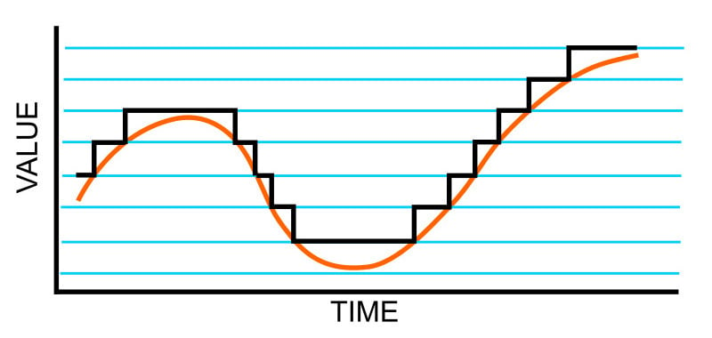
The black line below shows a digital signal over time, and the red line shows the converted analog signal over the same amount of time.
Once that analog signal has been converted by the ADC, the microcontroller can use those digital values any way you like!
Potentiometers
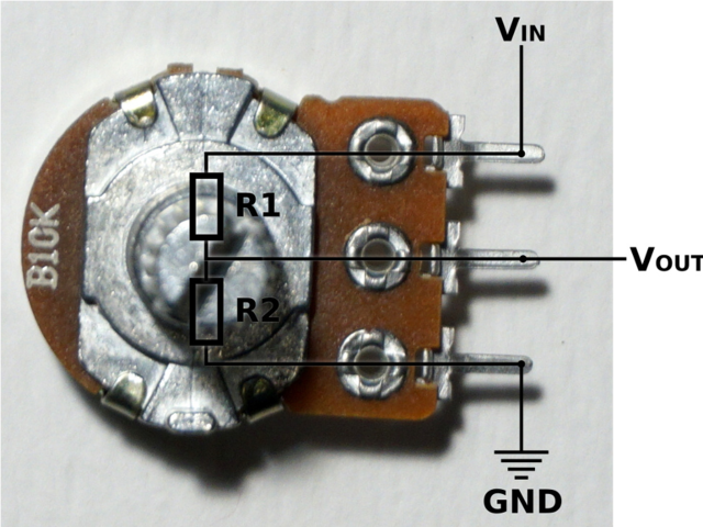
A potentiometer is a small variable resistor that you can twist a knob or shaft to change its resistance. It has three pins. By twisting the knob on the potentiometer you can change the resistance of the middle pin (called the wiper) to be anywhere within the range of resistance of the potentiometer.
By wiring the potentiometer to your board in a special way (called a voltage divider) you can turn the change in resistance into a change in voltage that your board’s analog to digital converter can read.
To wire up a potentiometer as a voltage divider:
- Connect one outside pin to ground
- Connect the other outside pin to voltage in (e.g. 3.3V)
- Connect the middle pin to an analog pin (e.g. A0)
Hardware
In addition to your microcontroller board, you will need the following hardware to follow along with this example.
Potentiometer

- Potentiometer left pin (white wire) to Feather A0
- Potentiometer center pin (red wire) to Feather 3.3V
- Potentiometer right pin (black wire) to Feather GND
Reading Analog Pin Values
CircuitPython makes it easy to read analog pin values. Simply import two modules, set up the pin, and then print the value inside a loop.
You'll need to connect to the serial console to see the values printed out.
In the example below, click the Download Project Bundle button below to download the necessary libraries and the code.py file in a zip file. Extract the contents of the zip file, open the directory CircuitPython_Templates/analog_pin_values/ and then click on the directory that matches the version of CircuitPython you're using and copy the contents of that directory to your CIRCUITPY drive.
Your CIRCUITPY drive should now look similar to the following image:

# SPDX-FileCopyrightText: 2021 Kattni Rembor for Adafruit Industries
# SPDX-License-Identifier: MIT
"""CircuitPython analog pin value example"""
import time
import board
import analogio

analog_pin = analogio.AnalogIn(board.A0)

while True:
    print(analog_pin.value)
    time.sleep(0.1)
Now, rotate the potentiometer to see the values change.
What do these values mean? In CircuitPython ADC values are put into the range of 16-bit unsigned values. This means the possible values you’ll read from the ADC fall within the range of 0 to 65535 (or 2^16 - 1). When you twist the potentiometer knob to be near ground, or as far to the left as possible, you see a value close to zero.
When you twist it to the right, the value gets bigger up to some value that is dependent on the microcontroller. Many microcontrollers get a value very close to 65535. Some, such as the ESP32-S2/S3, have a smaller limit of about 51000 or 2.57 volts.
The code is simple. You begin by importing three modules: time, board and analogio. All three modules are built into CircuitPython, so you don't need to download anything to get started.
Then, you set up the analog pin by creating an analogio.AnalogIn() object, providing it the desired pin using the board module, and saving it to the variable analog_pin.
Finally, in the loop, you print out the analog value with analog_pin.value, including a time.sleep() to slow down the values to a human-readable rate.
Reading Analog Voltage Values
These values don't necessarily equate to anything obvious. You can get an idea of the rotation of the potentiometer based on where in the range the value falls, but not without doing some math. Remember, you wired up the potentiometer as a voltage divider. By adding a simple function to your code, you can get a more human-readable value from the potentiometer.
You'll need to connect to the serial console to see the values printed out.
In the example below, click the Download Project Bundle button below to download the necessary libraries and the code.py file in a zip file. Extract the contents of the zip file, open the directory CircuitPython_Templates/analog_voltage_values_ESP32-S2/ and then click on the directory that matches the version of CircuitPython you're using and copy the contents of that directory to your CIRCUITPY drive.
Your CIRCUITPY drive should now look similar to the following image:

# SPDX-FileCopyrightText: 2022 Kattni Rembor for Adafruit Industries
# SPDX-License-Identifier: MIT
"""CircuitPython Analog In Voltage Example for ESP32-S2"""
import time
import board
import analogio

analog_pin = analogio.AnalogIn(board.A0)


def get_voltage(pin):
    return (pin.value * 2.57) / 51000


while True:
    print(get_voltage(analog_pin))
    time.sleep(0.1)
Now, rotate the potentiometer to see the values change.
Now the values range from around 0 to 2.57! Note that due to variations in each chip, you may not get all the way to 0 or 2.57, and in some cases, you may exceed 2.57. Both of these possibilities are normal.
The example code begins with the same imports and pin setup.
This time, you include the get_voltage helper. This function requires that you provide an analog pin. It then maps the raw analog values, 0 to 51000, to the voltage values, 0 to 2.57. It does the math so you don't have to!
Finally, inside the loop, you provide the function with your analog_pin, and print the resulting values.
That's all there is to reading analog voltage values using CircuitPython!


