You can easily wire this breakout to any microcontroller, we'll be using an Adafruit Metro (Arduino compatible) with the Arduino IDE. But, you can use any other kind of microcontroller as well as long as it has I2C clock and I2C data lines. Note this chip uses clock stretching so make sure your microcontroller supports that in hardware!


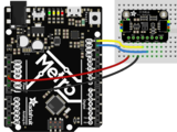

- Connect Vin (red wire on STEMMA QT version) to the power supply, 3-5V is fine. Use the same voltage that the microcontroller logic is based off of. For most Arduinos, that is 5V
- Connect GND (black wire on STEMMA QT version) to common power/data ground
- Connect the SCL (yellow wire on STEMMA QT version) pin to the I2C clock SCL pin on your Arduino.
On an UNO & '328 based Arduino, this is also known as A5, on a Mega it is also known as digital 21 and on a Leonardo/Micro, digital 3 - Connect the SDA (blue wire on STEMMA QT version) pin to the I2C data SDA pin on your Arduino.
On an UNO & '328 based Arduino, this is also known as A4, on a Mega it is also known as digital 20 and on a Leonardo/Micro, digital 2 - NOT NEEDED FOR STEMMA QT VERSION: Connect the WAKE pin to ground on the original version only.
This sensor uses I2C address 0x5A.
Download Adafruit_CCS811 library
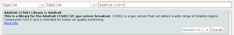
To begin reading sensor data, you will need to download Adafruit_CCS811 from the Arduino library manager.
Open up the Arduino library manager:

Search for the Adafruit CCS811 library and install it
We also have a great tutorial on Arduino library installation at:
http://learn.adafruit.com/adafruit-all-about-arduino-libraries-install-use
Load Test Example
Open up File->Examples->Adafruit_CCS811->CCS811_test and upload to your Arduino wired up to the sensor. This example connects to the sensor and starts taking readings.

Once uploaded to your Arduino, open up the serial console at 9600 baud speed to see the readings. Your sensor will take 3 zero readings while it does some internal calibration and correction things and then start outputting real data. In clean air and a typical indoor space your serial monitor will look something like this:

Adafruit_CCS811 ccs;
initialize the sensor with:
if(!ccs.begin()){
    Serial.println("Failed to start sensor! Please check your wiring.");
    while(1);
  }
To poll the sensor for available data you can use:
bool dataAvailable = ccs.available(); //returns true if data is available to be read
Data can be read using:
bool error = ccs.readData(); //returns True if an error occurs during the read
and then the readings can be accessed with:
int eCO2 = ccs.geteCO2(); //returns eCO2 reading
int TVOC = ccs.getTVOC(); //return TVOC reading
Approximate ambient temperature can be read using:
float temp = ccs.calculateTemperature();


