
CircuitPython and Python
It's easy to use the ADS122C04 with Python or CircuitPython, and the Adafruit_CircuitPython_ADS122C04 module. This module allows you to easily write Python code to read the 4 analog inputs on the ADC.
You can use this driver with any CircuitPython microcontroller board or with a computer that has GPIO and Python thanks to Adafruit_Blinka, our CircuitPython-for-Python compatibility library.
CircuitPython Microcontroller Wiring
First wire up the breakout to your board exactly as follows. The following is the breakout wired to a Feather RP2040 using the STEMMA connector along with a potentiometer connected to analog input 0 (A0) on the ADC:

-
Board STEMMA 3V to breakout VIN (red wire)
-
Board STEMMA GND to breakout GND (black wire)
-
Board STEMMA SCL to breakout SCL (yellow wire)
- Board STEMMA SDA to breakout SDA (blue wire)
- Breakout VIN to potentiometer positive (red wire)
- Breakout A0 to potentiometer wiper (green wire)
- Breakout GND to potentiometer negative (black wire)
- Breakout VIN to breakout Ref+ (red wire)
- Breakout GND to breakout Ref- (black wire)

The following is the breakout wired to a Feather RP2040 using a solderless breadboard:

-
Board 3V to breakout VIN (red wire)
-
Board GND to breakout GND (black wire)
-
Board SCL to breakout SCL (yellow wire)
- Board SDA to breakout SDA (blue wire)
- Breakout VIN to potentiometer positive (red wire)
- Breakout A0 to potentiometer wiper (green wire)
- Breakout GND to potentiometer negative (black wire)
- Breakout VIN to breakout Ref+ (red wire)
- Breakout GND to breakout Ref- (black wire)
Python Computer Wiring
Since there are dozens of Linux computers/boards you can use, we will show wiring for Raspberry Pi. For other platforms, please visit the guide for CircuitPython on Linux to see whether your platform is supported.
Here's the Raspberry Pi wired with I2C using the STEMMA connector:

-
Pi 3V to breakout VIN (red wire)
-
Pi GND to breakout GND (black wire)
-
Pi SCL to breakout SCL (yellow wire)
- Pi SDA to breakout SDA (blue wire)
- Breakout VIN to potentiometer positive (red wire)
- Breakout A0 to potentiometer wiper (green wire)
- Breakout GND to potentiometer negative (black wire)
- Breakout VIN to breakout Ref+ (red wire)
- Breakout GND to breakout Ref- (black wire)
Here's the Raspberry Pi wired with I2C using a solderless breadboard:

-
Pi 3V to breakout VIN (red wire)
-
Pi GND to breakout GND (black wire)
-
Pi SCL to breakout SCL (yellow wire)
- Pi SDA to breakout SDA (blue wire)
- Breakout VIN to potentiometer positive (red wire)
- Breakout A0 to potentiometer wiper (green wire)
- Breakout GND to potentiometer negative (black wire)
- Breakout VIN to breakout Ref+ (red wire)
- Breakout GND to breakout Ref- (black wire)
Python Installation of ADS122C04 Library
You'll need to install the Adafruit_Blinka library that provides the CircuitPython support in Python. This may also require enabling I2C on your platform and verifying you are running Python 3. Since each platform is a little different, and Linux changes often, please visit the CircuitPython on Linux guide to get your computer ready!
Once that's done, from your command line run the following command:
pip3 install adafruit-circuitpython-ads122c04
If your default Python is version 3 you may need to run 'pip' instead. Just make sure you aren't trying to use CircuitPython on Python 2.x, it isn't supported!
CircuitPython Usage
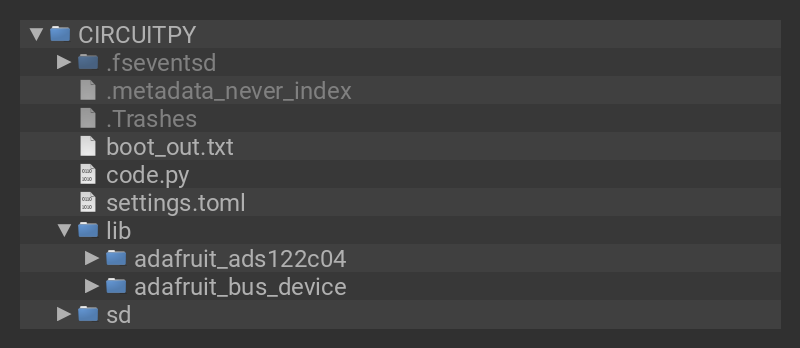
To use with CircuitPython, you need to first install the Adafruit_CircuitPython_ADS122C04 library, and its dependencies, into the lib folder on your CIRCUITPY drive. Then you need to update code.py with the example script.
Thankfully, we can do this in one go. In the example below, click the Download Project Bundle button below to download the necessary libraries and the code.py file in a zip file. Extract the contents of the zip file, and copy the entire lib folder and the code.py file to your CIRCUITPY drive.
Your CIRCUITPY/lib folder should contain the following folders:
- adafruit_bus_device/
- adafruit_ads122c04/
Python Usage
Once you have the library pip3 installed on your computer, copy or download the following example to your computer, and run the following, replacing code.py with whatever you named the file:
python3 code.py
Example Code
If running CircuitPython: Once everything is saved to the CIRCUITPY drive, connect to the serial console to see the data printed out!
If running Python: The console output will appear wherever you are running Python.
# SPDX-FileCopyrightText: Copyright (c) 2026 Liz Clark for Adafruit Industries
#
# SPDX-License-Identifier: MIT

import time

import board

from adafruit_ads122c04.ads122c04 import ADS122C04, VREF_EXTERNAL
from adafruit_ads122c04.analog_in import AnalogIn

i2c = board.I2C()
adc = ADS122C04(i2c)

chan0 = AnalogIn(adc, 0)
chan1 = AnalogIn(adc, 1)
chan2 = AnalogIn(adc, 2)
chan3 = AnalogIn(adc, 3)

channels = (chan0, chan1, chan2, chan3)

adc.vref_input = VREF_EXTERNAL
adc.reference_voltage = 3.3

while True:
    for i, chan in enumerate(channels):
        print(f"A{i}: {chan.value:5d}  ({chan.voltage:.4f} V)")
    print("-" * 30)
    time.sleep(1)
The ADS122C04 is initialized over I2C. Then in the loop, the analog input on A0 is read and printed to the serial monitor. As you adjust the potentiometer connected to A0, you'll see the values change.

Strain Gauge Load Cell Usage
Here's an example of using the ADS122C04 with a 1Kg strain gauge load cell as a scale, connected to a Feather TFT ESP32-S2.
# SPDX-FileCopyrightText: 2026 John Park w Claud AI Opus 4.8 for Adafruit Industries
# SPDX-License-Identifier: MIT

"""
ADS122C04 24-bit ADC - 1kg Load Cell Scale on Feather ESP32-S2 TFT
Differential, ratiometric bridge read with live readout on the built-in
240x135 color TFT. BOOT button (D0) re-tares.

Wiring:
  Feather 3V             -> ADS122C04 REF+
  Feather GND            -> ADS122C04 REF-
  Load cell Red   (E+)   -> REF+
  Load cell Black (E-)   -> REF-
  Load cell Green (S+)   -> A0
  Load cell White (S-)   -> A1
  STEMMA QT cable        -> I2C + chip power

Libraries (circup install ...):
  adafruit_ads122c04
  adafruit_display_text

NOTE on the BOOT button:
  On this board the BOOT button is exposed as board.BUTTON (same pin as
  board.BOOT0). It is pulled HIGH at rest and goes LOW when pressed, so use
  a pull-up and treat `not button.value` as a press. It's also the
  bootloader button, so only press it while code is running, never during
  reset/plug-in.
"""

import time
import board
import digitalio
import terminalio
import displayio
from adafruit_display_text import label
from adafruit_ads122c04.ads122c04 import (
    ADS122C04,
    GAIN_64,
    MUX_AIN0_AIN1,
    VREF_EXTERNAL,
)

# ── Configuration ──────────────────────────────────────────────────────────────

ADC_GAIN = GAIN_64
SCALE_FACTOR = 255.50  # counts/gram, recalibrated with 508.3g
LOAD_CELL_CAPACITY_G = 1000.0

NUM_SAMPLES = 8
TARE_SAMPLES = 32
DEAD_BAND_G = 0.3        # below this, display shows a clean 0.0 g

# Auto-zero tracking — cancels slow load-cell creep/drift so an empty
# platform always settles to 0.0 g, while real loads still read through.
#   AZ_WINDOW_G : reading must be within +/- this of zero to be "near empty"
#   AZ_RATE     : fraction of the residual nudged out each update (0..1).
#                 Small = gentle/slow correction; large = aggressive.
#   AZ_HOLD     : consecutive near-zero readings required before tracking
#                 kicks in (debounce so a real load isn't auto-zeroed away).
AZ_ENABLED = True
AZ_WINDOW_G = 3.0
AZ_RATE = 0.25
AZ_HOLD = 3

# Signed 24-bit limits
ADC_MAX = 8388607
ADC_MIN = -8388608

# Colors
BG = 0x000000
ACCENT = 0x00E0C0
WHITE = 0xFFFFFF
DIM = 0x808080

# ── ADC init ───────────────────────────────────────────────────────────────────

i2c = board.STEMMA_I2C()
adc = ADS122C04(i2c)

adc.mux = MUX_AIN0_AIN1     # differential AINP=A0, AINN=A1
adc.vref_input = VREF_EXTERNAL
adc.reference_voltage = 3.3
adc.pga = True
adc.gain = ADC_GAIN

# ── BOOT button — exposed as board.BUTTON, active LOW ──────────────────────────

button = digitalio.DigitalInOut(board.BUTTON)
button.switch_to_input(pull=digitalio.Pull.UP)

# ── Display setup ──────────────────────────────────────────────────────────────

display = board.DISPLAY
group = displayio.Group()

# Solid background
bg_bitmap = displayio.Bitmap(display.width, display.height, 1)
bg_palette = displayio.Palette(1)
bg_palette[0] = BG
group.append(displayio.TileGrid(bg_bitmap, pixel_shader=bg_palette))

# Title
title = label.Label(terminalio.FONT, text="LOAD CELL", color=ACCENT, scale=2)
title.anchor_point = (0.5, 0.0)
title.anchored_position = (display.width // 2, 6)
group.append(title)

# Big weight readout (grams)
weight_label = label.Label(terminalio.FONT, text="0.0 g", color=WHITE, scale=4)
weight_label.anchor_point = (0.5, 0.5)
weight_label.anchored_position = (display.width // 2, display.height // 2)
group.append(weight_label)

# Secondary units line
units_label = label.Label(terminalio.FONT, text="", color=DIM, scale=2)
units_label.anchor_point = (0.5, 1.0)
units_label.anchored_position = (display.width // 2, display.height - 8)
group.append(units_label)

display.root_group = group

# ── Differential read ──────────────────────────────────────────────────────────

def read_raw():
    """Trigger one conversion and return the signed 24-bit result."""
    adc.mux = MUX_AIN0_AIN1        # reassert each read
    adc.start_sync()
    while not adc.data_ready:
        pass
    return adc.read_data()


def read_average(samples=NUM_SAMPLES):
    total = 0
    for _ in range(samples):
        total += read_raw()
        time.sleep(0.005)
    return total / samples


def set_status(text, color=ACCENT):
    title.text = text
    title.color = color


def tare(samples=TARE_SAMPLES):
    set_status("TARING…", ACCENT)
    weight_label.text = "----"
    zero = read_average(samples)
    set_status("LOAD CELL", ACCENT)
    return zero


# ── Startup ────────────────────────────────────────────────────────────────────

tare_value = tare()
prev_pressed = False
az_count = 0  # consecutive near-zero readings, for auto-zero debounce

# ── Main loop ──────────────────────────────────────────────────────────────────

while True:
    # BOOT button (active LOW) edge-detect -> manual re-tare
    pressed = not button.value
    if pressed and not prev_pressed:
        tare_value = tare()
        az_count = 0
    prev_pressed = pressed

    raw = read_average()
    net = raw - tare_value
    weight_g = net / SCALE_FACTOR if SCALE_FACTOR else 0.0

    # ── Auto-zero tracking ──────────────────────────────────────────────────
    # If the reading sits near zero for AZ_HOLD samples in a row, treat it as
    # an empty platform and gently pull the tare toward the current raw value
    # to cancel slow creep/thermal drift. A real load (outside AZ_WINDOW_G)
    # resets the counter, so it's never auto-zeroed away.
    if AZ_ENABLED and abs(weight_g) < AZ_WINDOW_G:
        az_count += 1
        if az_count >= AZ_HOLD:
            tare_value += (raw - tare_value) * AZ_RATE
            net = raw - tare_value
            weight_g = net / SCALE_FACTOR if SCALE_FACTOR else 0.0
    else:
        az_count = 0

    # Final dead-band so the display reads a clean 0.0 g when empty
    if abs(weight_g) < DEAD_BAND_G:
        weight_g = 0.0

    weight_oz = weight_g / 28.3495
    weight_lb = weight_g / 453.592

    weight_label.text = f"{weight_g:.1f} g"
    units_label.text = f"{weight_oz:.2f} oz  {weight_lb:.3f} lb"

    # Also print to serial for logging
    print(f"{weight_g:7.1f} g  ({weight_oz:5.2f} oz / {weight_lb:5.3f} lb)")

    time.sleep(0.15)
Page last edited June 15, 2026


