Easy e-paper finally comes to microcontrollers with these breakouts, shields and friends that are designed to make it a breeze to add a tri-color eInk display. Chances are you've seen one of those new-fangled 'e-readers' like the Kindle or Nook. They have gigantic electronic paper 'static' displays - that means the image stays on the display even when power is completely disconnected. The image is also high contrast and very daylight readable. It really does look just like printed paper!

Adafruit has liked these displays for a long time, but they were never designed for makers to use. Finally, we decided to make our own!

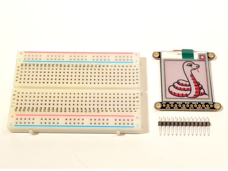
We have multiple 2.13" EPD displays:
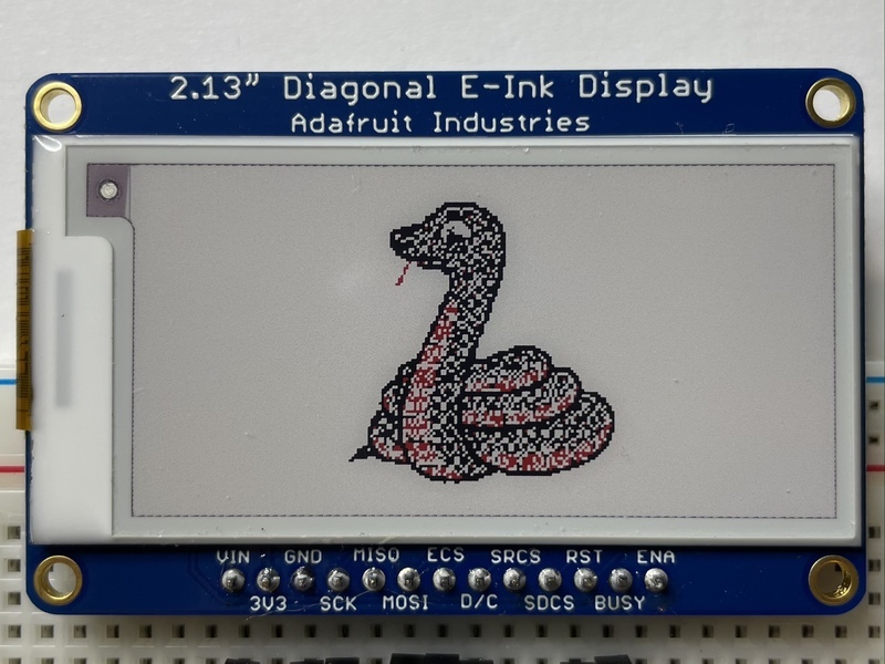
Using our Arduino library, you can create a 'frame buffer' with what pixels you want to have activated and then write that out to the display. Most simple breakouts leave it at that. But if you do the math, using even the smallest 2.13" display: 212 x 104 pixels = 2.5 KBytes. Which won't fit into many microcontroller memories. Heck, even if you do have 32KB of RAM, why waste 2.5KB?

So we did you a favor and tossed a small SRAM chip on the back. This chip shares the SPI port the eInk display uses, so you only need one extra pin. And, no more frame-buffering! You can use the SRAM to set up whatever you want to display, then shuffle data from SRAM to eInk when you're ready. The library we wrote does all the work for you, you can just interface with it as if it were an Adafruit_GFX compatible display.

For ultra-low power usages, the onboard 3.3V regulator has the Enable pin brought out so you can shut down the power to the SRAM, MicroSD and display.

We even added on a MicroSD socket to the breakouts and FeatherWings so you can store images, text files, whatever you like to display. Everything is 3 or 5V logic safe so you can use it with any and all common Maker microcontrollers.

This e-Paper display uses SPI to receive image data. Since the display is SPI, it was easy to add two more SPI devices to share the bus - an SPI SRAM chip and SPI-driven SD card holder. There's quite a few pins and a variety of possible combinations for control depending on your needs

2.13" E-Ink display Breakout

Used for Monochrome or Tri-Color displays that are not flexible. This format is very breadboard-friendly!

eInk Breakout Friend

Connect a bare eInk display to this breakout to use it, perfect for our 2.13" flexible displays

EYESPI

The 2.13" 250x122 Tri-Color eInk now comes with an EYESPI connector, which is an 18pin 0.5mm pitch connector that allows you to use a flex cable to connect your display to your microcontroller. For more details, visit the EYESPI page.

Power Pins

  • 3-5V / Vin - this is the power pin, connect to 3-5VDC - it has reverse polarity protection but try to wire it right!
  • 3.3V out - this is the 3.3V output from the onboard regulator, you can 'borrow' about 100mA if you need to power some other 3.3V logic devices
  • GND - this is the power and signal ground pin
  • ENAble - This pin is all the way on the right. It is connected to the enable pin on the onboard regulator that powers everything. If you want to really have the lowest possible power draw, pull this pin low! Note that, if you do so, you will cut power to the eInk display but also the SPI RAM (thus erasing it) and the SD card (which means you'll have to re-initialize it when you re-power

Data Control Pins

  • SCK - this is the SPI clock input pin, required for e-Ink, SRAM and SD card
  • MISO - this is the SPI Microcontroller In Serial Out pin, its used for the SD card and SRAM. It isn't used for the e-Ink display which is write-only, however you'll likely be using the SRAM to buffer the display so connect this one too!
  • MOSI - this is the SPI Microcontroller Out Serial In pin, it is used to send data from the microcontroller to the SD card, SRAM and e-Ink display
  • ECS - this is the E-Ink Chip Select, required for controlling the display
  • D/C - this is the e-Ink Data/Command pin, required for controlling the display
  • SRCS - this is the SRAM Chip Select, required for communicating with the onboard RAM chip.
  • SDCS - this is the SD card Chip Select, required for communicating with the onboard SD card holder. You can leave this disconnected if you aren't going to access SD cards
  • RST - this is the E-Ink ReSeT pin, you may be able to share this with your microcontroller reset pin but if you can, connect it to a digital pin.
  • BUSY - this is the e-Ink busy detect pin, and is optional if you don't want to connect the pin (in which case the code will just wait an approximate number of seconds)

FeatherWing Connections

The FeatherWing eInk Display and eInk Feather Friend are a little more compact but have just about the same pins as the breakout

  • SPI MOSI/MISO/SCK are on the FeatherWing SPI connection pads

SD CS, SRAM CS, EINK CS and DC are in order after the two I2C pins. The numbers of the pins these correspond to will differ from board to board. However, on 32u4/328p/M0/M4/nRF52840 and many other boards you will see the following connections

  • SD CS to Pin D5
  • SRAM CS to Pin D6
  • EINK CS to Pin D9
  • EINK DC to Pin D10

If you do not plan to use the SD card, you can cut the trace to SD CS. Likewise for SRAM CS.

The Reset pin for the E-Ink display is connected to an auto-reset circuit and also to the Feather Reset pin, so it will reset when you press the reset button.

The Busy pin is available on a breakout pad, you can solder it to a wire and connect to a pin if you need it - we figure most people will just use a fixed delay.

Currently, only the 2.13" Tri-Color eInk display has been updated to have an EYESPI connector.
backview

This display now comes with an EYESPI connector. This connector allows you to connect your display without soldering. There are EYESPI cables available in multiple lengths, which means you can find one to fit any project. This is especially useful if your project requires the display to be freestanding, and not tied directly into a breadboard. Inspired by the popularity of STEMMA QT, it provides plug-n-play for displays!

The EYESPI Connector and Cables

The EYESPI connector is an 18 pin 0.5mm pitch FPC connector with a flip-top tab for locking in the associated flex cable. It is designed to allow you to connect a display, without needing to solder headers or wires to the display.

The EYESPI connector location on this display is indicated below.

The EYESPI cables are 18 pin 0.5mm pitch flex cables. They are ~9.6mm wide, and designed to fit perfectly into the EYESPI connector. Adafruit currently offers EYESPI cables in three different lengths: 50mm, 100mm, and 200mm.

The EYESPI connector is designed to work with 18-pin 0.5mm pitch flex cables. Other flex cables, such as Raspberry Pi camera flex cables, will not work!

Wiring Your EYESPI Display

Wiring your EYESPI display to a microcontroller via the EYESPI connector requires the EYESPI breakout board and an EYESPI cable.

Overhead video of a 1.9" TFT display connected via 18-pin FPC ribbon cable to a square-shaped microcontroller on a breadboard. The TFT plays an animated boot-up demo.
Our most recent display breakouts have come with a new feature: an 18-pin "EYE SPI" standard FPC...
$1.95
In Stock
Angled shot of a EYESPI Cable - 18 Pin 100mm long Flex PCB (FPC) A-B type.
Connect this to that when a 18-pin FPC connector is needed. This 25 cm long cable is made of a flexible PCB. It's A-B style which means that pin one on one side will match...
$0.95
In Stock

The following example shows how to connect the 2.13" eInk display to a Feather RP2040 using the EYESPI breakout board.

Connect the following Feather pins to the associated EYESPI breakout pins:

  • Breakout Vin to Feather Vin (red wire)
  • Breakout Gnd to Feather Gnd (black wire)
  • Breakout SCK to Feather SCK (blue wire)
  • Breakout MOSI to Feather MOSI (yellow wire)
  • Breakout MISO to Feather MISO (green wire)
  • Breakout MEMCS to Feather pin 6 (pink wire)
  • Breakout TCS to Feather pin 9 (grey wire)
  • Breakout DC to Feather pin 10 (white wire)
  • Breakout RST to Feather pin 11 (orange wire)
  • Breakout BUSY to Feather pin 12 (cyan wire)
  • Breakout SDCS to Feather pin 13 (purple wire)

Finally, connect your display EYESPI connector to the breakout EYESPI connector using an EYESPI cable. For details on using the EYESPI connector properly, visit Plugging in an EYESPI Cable.

EYESPI Pins

Though there are 18 pins available on the EYESPI connector, many displays do not use all available pins. This display requires the following pins:

  • Vin - This is the power pin. To power the board (and thus your display), connect to the same power as the logic level of your microcontroller, e.g. for a 3V micro like a Feather, use 3V, and for a 5V micro like an Arduino, use 5V
  • GND - This is common ground for power and logic
  • SCK - This is the SPI clock input pin
  • MOSI - This is the SPI MOSI (Microcontroller Out / Serial In) pin. It is used to send data from the microcontroller to the SD card and/or display
  • MISO - This is the SPI MISO (Microcontroller In / Serial Out) pin. It's used for the SD card. It isn't used for the display because it's write-only. It is 3.3V logic out (but can be read by 5V logic)
  • TCS - eInk Chip Select pin
  • DC - Data/command pin
  • MEMCS - Memory Chip Select, required for communicating with the onboard RAM chip
  • RST - This is the display reset pin. Connecting to ground resets the display! It's best to have this pin controlled by the library so the display is reset cleanly, but you can also connect it to the microcontroller's Reset pin, which works for most cases. Often, there is an automatic-reset chip on the display which will reset it on power-up, making this connection unnecessary in that case
  • BUSY - e-Ink busy detect pin
  • SDCS - This is the SD card chip select pin. This pin is required for communicating with the SD card holder onboard the connected display

You can connect an EYESPI compatible display to the EYESPI breakout board using an EYESPI cable. An EYESPI cable is an 18 pin flexible PCB (FPC). The FPC can only be connected properly in one orientation, so be sure to follow the steps below to ensure that your display and breakout are plugged in properly.

Each EYESPI cable has blue stripes on either end. On the other side of the cable, underneath the blue stripe, are the connector pins that make contact with the FPC connector pins on the display or breakout.

To begin inserting an EYESPI cable to an FPC connector, gently lift the FPC connector black latch up. 

Then, insert the EYESPI cable into the open FPC connector by sliding the cable into the connector. You want to see the blue stripe facing up towards you. This inserts the cable pins into the FPC connector.

To secure the cable, lower the FPC connector latch onto the EYESPI cable.

Repeat this process for the FPC connector on your display. Again, ensure that the blue stripe on either end of the cable is facing up.

Assembly

Cut the header down to length if necessary. It will be easier to solder if you insert it into a breadboard - long pins down

Add the E-Ink Display


Place the board over the pins so that the short pins poke through the top of the breakout pads

And Solder!


Be sure to solder all pins for reliable electrical contact.

(For tips on soldering, be sure to check out the Guide to Excellent Soldering).

OK, you're done!

Breakout Wiring

Though it looks like a lot of connections, wiring up an eInk breakout is pretty straightforward! Below shows using hardware SPI to connect it to an Adafruit Metro M4.

  • Vin connects to the microcontroller board's 5V or 3.3V power supply pin
  • GND connects to ground
  • CLK connects to SPI clock. It's easiest to connect it to pin 3 of the ICSP header.
  • MOSI connects to SPI MOSI. It's easiest to connect it to pin 4 of the ICSP header.
  • MISO connects to SPI MISO. It's easiest to connect it to pin 1 of the ICSP header.
  • ECS connects to our e-Ink Chip Select pin. We'll be using Digital 9
  • D/C connects to our e-Ink data/command select pin. We'll be using Digital 10.
  • SRCS connects to our SRAM Chip Select pin. We'll be using Digital 6
  • RST connects to our e-Ink reset pin. We'll be using Digital 8.
  • BUSY connects to our e-Ink busy pin. We'll be using Digital 7.
  • SDCS connects to our SD Card Chip Select pin. We'll be using Digital 5

Flexible Display and eInk Breakout Friend Wiring

  • Vin connects to the microcontroller board's 5V or 3.3V power supply pin
  • GND connects to ground
  • CLK connects to SPI clock. It's easiest to connect it to pin 3 of the ICSP header.
  • MOSI connects to SPI MOSI. It's easiest to connect it to pin 4 of the ICSP header.
  • MISO connects to SPI MISO. It's easiest to connect it to pin 1 of the ICSP header.
  • ECS connects to our e-Ink Chip Select pin. We'll be using Digital 9
  • D/C connects to our e-Ink data/command select pin. We'll be using Digital 10.
  • SRCS connects to our SRAM Chip Select pin. We'll be using Digital 6
  • RST connects to our e-Ink reset pin. We'll be using Digital 8.
  • BUSY connects to our e-Ink busy pin. We'll be using Digital 7.

FeatherWing Connection

FeatherWing usage is easy, simply plug your Feather into the Wing

Python Wiring

The wiring for the eInk Breakout and eInk Breakout Friend to the Raspberry Pi is the same.

  • Raspberry Pi 3.3 to display VIN
  • Raspberry Pi GND to display GND
  • Raspberry Pi SCLK to display SCK
  • Raspberry Pi MOSI to display MOSI
  • Raspberry Pi GPIO CE0 to display ECS
  • Raspberry Pi GPIO 22 to display D/C
  • Raspberry Pi GPIO 27 to display RST
  • Raspberry Pi GPIO 17 to display BUSY

Flexible Display/eInk Breakout Friend

One thing to remember with these small e-Ink screens is that its very slow compared to OLEDs, TFTs, or even 'memory displays'. It will take may seconds to fully erase and replace an image

There's also a recommended limit on refeshing - you shouldn't refresh or change the display more than every 3 minutes (180 seconds).

You don't have to refresh often, but with tri-color displays, the larger red ink dots will slowly rise, turning the display pinkish instead of white background. To keep the background color clear and pale, refresh once a day

Do not update more than once every 180 seconds or you may permanently damage the display

To use the display, you will need to install the Adafruit_EPD library (code on our github repository). It is available from the Arduino library manager so we recommend using that.

From the IDE open up the library manager...

And type in adafruit EPD to locate the library. Click Install

If you would like to draw bitmaps, do the same with adafruit ImageReader, click Install

Do the same to install the latest adafruit GFX library, click Install

If using an earlier version of the Arduino IDE (pre-1.8.10), locate and install Adafruit_BusIO (newer versions handle this prerequisite automatically).

Here is where the differences in the tri-color/monochrome and chipset/dimensions start mattering. Check carefully to make sure you are running the right example and creating the matching ThinkInk type for your display or you won't see anything happen on the EPD (or the image may be really weird looking).

2.13" Monochrome 250x122 Pixel Display

For the 250 x 122 monochrome display, 250 x 122 monochrome FeatherWing, or 212x104 Flexible Display we will run a monochrome demo.

Front of E-Ink display with monochrome graphic and "2.13 inch E-Ink Monochrome" text
Easy e-paper finally comes to microcontrollers, with this breakout that's designed to make it a breeze to add a monochromatic eInk display. Chances are you've seen one of those...
$22.50
In Stock
E-Ink display connected to Feather, refreshing itself
Easy e-paper finally comes to your Feather, with this breakout that's designed to make it a breeze to add a monochrome eInk display. Chances are you've seen one of those...
Out of Stock
Hands flexing a 2.13" Flexible Monochrome E-Ink display.
Woah, the cyber-future is here! Flexible E-Ink has been demo'd at high-tech events for years but now you can actually get your paws on it. This display is true E-Ink / E-Paper,...
Out of Stock

Open up FileExamplesAdafruit_EPDThinkInk_mono

If you are not sure whether you have an older or newer display, you can try both drivers and see which one works.

2.13" Tri-Color 250x122 OR 212x104 Pixel Display

For the 250x122 OR 212x104 Tri-Color display, we will run the tricolor demo.

Video of a 2.13" tri-color eInk display assembled on a breadboard with jumper wires and a QT Py. Friendly snake in white-and-red, Blinka, appears on the display.
Easy e-paper finally comes to microcontrollers, with this breakout that's designed to make it a breeze to add a tri-color eInk display. Chances are you've seen one of those...
$19.95
In Stock
E-Ink display connected to Feather,  with image of friendly snake
Easy e-paper comes to your Feather, with this breakout that's designed to make it a breeze to add a tri-color eInk display. Chances are you've seen one of those new-fangled...
Out of Stock
The demo updates every 15 seconds which is fine for demonstrating the functionality for a short time, but we recommend not updating more often than 180 seconds if you are planning on running any code long term.

Open up FileExamplesAdafruit_EPD→ThinkInk_tricolor

Configure Pins

For the FeatherWing you must be sure both EPD_RESET and EPD_BUSY are set to -1 since neither of these lines are connected or the E-Ink will not update.

No matter what display you have, you will need to verify that your pins match your wiring. At the top of the sketch find the lines that look like:

#define EPD_DC      10
#define EPD_CS      9
#define SRAM_CS     6
#define EPD_RESET   8 // can set to -1 and share with microcontroller Reset!
#define EPD_BUSY    7 // can set to -1 to not use a pin (will wait a fixed delay)

If you are using the FeatherWing only: Change both EPD_RESET and EPD_BUSY to -1 since neither of these lines are connected on the FeatherWing.

If you wired the display differently than on the wiring page, adjust the pin numbers accordingly.

Configure Display Type & Size

Find the part of the script where you can pick which display is going to be used. The eInk displays are made up a combination of a Chipset and a Film in different sizes. We have narrowed it down to just a few choices between the size of the display, chipset, and film based on available combinations. In the sketch, we have sorted it by size, so it's easy to find your display.

You will need to uncomment the appropriate initializer and and leave any other type commented.

For the older 2.13" 250x122 Monochrome breakout or 2.13" 250x122 Monochrome FeatherWing with SSD1675, you will use ThinkInk_213_Mono_B72 display initializer.

For the newer 2.13" 250x122 Monochrome breakout or 2.13" 250x122 Monochrome FeatherWing with SSD1680, you can use either theThinkInk_213_Mono_BN or the ThinkInk_213_Mono_B74 display initializer.

For the 2.13" 212x104 Monochrome Flexible Display, you will use the ThinkInk_213_Mono_M21 display initializer.

For the 2.13" 250x122 Tri-Color breakout or 2.13" 250x122 Tri-Color FeatherWing, you will use the ThinkInk_213_Tricolor_RW display initializer.

For the 2.13" 212x104 Tri-Color breakout or 2.13" 212x104 Tri-Color FeatherWing, you will use the ThinkInk_213_Tricolor_Z16 display initializer.

For example, for a tri-color 250x122, uncomment this line, and comment any other line that is creating a ThinkInk display object

// 2.13" Tricolor EPD with SSD1680 chipset
ThinkInk_213_Tricolor_RW display(EPD_DC, EPD_RESET, EPD_CS, SRAM_CS, EPD_BUSY);

Upload Sketch

After checking the pinouts and the display type one more time, go ahead and upload the sketch to your board. Once it is done uploading, open the Serial Monitor.

The display should start running a series of display tests

Not only can you draw shapes but you can also load images from the SD card, perfect for static images!

The 2.13 flexible e-Ink can show a max of 212x104 pixels and the non-flexible 2.13" Monochrome displays can show a max of 250x122 pixels. The older 2.13" Tri-Color displays can show a max of 212x104 pixels and the HD Tri-Color versions can show a max of 250x122 pixels. Let's use this Blinka bitmap for our demo. Select the one that is the correct size:

Download the blinka.bmp file, rename if necessary, and place it into the base directory of a microSD card and insert it into the microSD socket in the breakout.

Plug the MicroSD card into the display. You may want to try the SD library examples before continuing, especially one that lists all the files on the SD card

Open the file→examples→Adafruit_ImageReader→ThinkInkDisplays example

Upload to your board and you should see an image of Blinka appear.

If you want to later use your own image, use an image editing tool and crop your image to no larger than 212 pixels wide and 104 pixels high on the standard display and no larger than 250 pixels wide and 122 pixels high on the HD display. Save it as a 24-bit color BMP file - it must be 24-bit color format to work, even if it was originally a 16-bit color image - because of the way BMPs are stored and displayed!

Here is where the differences in the tri-color/monochrome and chipset/dimensions start mattering. Check carefully to make sure you are running the right example and creating the matching library type for your display or you won't see anything happen on the EPD (or the image may be really weird looking).

CircuitPython eInk displayio Library Installation

To use displayio, you will need to install the appropriate library for your display. 

First make sure you are running the latest version of Adafruit CircuitPython for your board. You will need the latest version of CircuitPython.

Next you'll need to install the necessary libraries to use the hardware--carefully follow the steps to find and install these libraries from Adafruit's CircuitPython library bundle.  The introduction guide has a great page on how to install the library bundle for both express and non-express boards.

You will need to copy the appropriate displayio driver from the bundle lib folder to a lib folder on your CIRCUITPY drive. The displayio driver contains the initialization codes specific to your display that are needed to for it to work. Since there is more than one driver, you will need to copy the correct file over. Here is a list of each of the displays and the correct driver for that display.

To use the eInk displays with displayio, you will need to use the latest version of CircuitPython and a board that can fit `displayio`. See the Support Matrix to determine if `displayio` is available on a given board: https://circuitpython.readthedocs.io/en/latest/shared-bindings/support_matrix.html

Adafruit_CircuitPython_SSD1675

The older 250x122 monochrome display with SSD1675 driver uses the Adafruit_CircuitPython_SSD1675 library. Copy the adafruit_ssd1675.mpy file from the bundle to the lib folder on your CIRCUITPY drive.

Front of E-Ink display with monochrome graphic and "2.13 inch E-Ink Monochrome" text
Easy e-paper finally comes to microcontrollers, with this breakout that's designed to make it a breeze to add a monochromatic eInk display. Chances are you've seen one of those...
$22.50
In Stock
E-Ink display connected to Feather, refreshing itself
Easy e-paper finally comes to your Feather, with this breakout that's designed to make it a breeze to add a monochrome eInk display. Chances are you've seen one of those...
Out of Stock
If you are not sure whether you have an older or newer display, you can try both drivers and see which one works.

Adafruit_CircuitPython_IL0373

The 212x104 Monochrome Flexible display, older 212x104 Tri-Color FeatherWing, and older 212x104 Tri-Color breakout use the Adafruit_CircuitPython_ILI0373 library. Copy the adafruit_il0373.mpy file from the bundle to the lib folder on your CIRCUITPY drive.

Hands flexing a 2.13" Flexible Monochrome E-Ink display.
Woah, the cyber-future is here! Flexible E-Ink has been demo'd at high-tech events for years but now you can actually get your paws on it. This display is true E-Ink / E-Paper,...
Out of Stock

Adafruit_CircuitPython_SSD1680

The newer 250x122 HD Tri-Color breakout display and 250x122 HD Tri-Color FeatherWing use the Adafruit_CircuitPython_SSD1680 library. Copy the adafruit_ssd1680.mpy file from the bundle to the lib folder on your CIRCUITPY drive.

The newer 250x122 monochrome display with SSD1680 driver and 250x122 Monochrome FeatherWing with SSD1680 driver use the Adafruit_CircuitPython_SSD1680 library as well. Copy the adafruit_ssd1680.mpy file from the bundle to the lib folder on your CIRCUITPY drive.

No modifications between the Tri-Color and Monochrome display initializers are necessary.

Video of a 2.13" tri-color eInk display assembled on a breadboard with jumper wires and a QT Py. Friendly snake in white-and-red, Blinka, appears on the display.
Easy e-paper finally comes to microcontrollers, with this breakout that's designed to make it a breeze to add a tri-color eInk display. Chances are you've seen one of those...
$19.95
In Stock
E-Ink display connected to Feather,  with image of friendly snake
Easy e-paper comes to your Feather, with this breakout that's designed to make it a breeze to add a tri-color eInk display. Chances are you've seen one of those new-fangled...
Out of Stock

Image File

To show you how to use the eInk with displayio, we'll show you how to draw a bitmap onto it. First start by downloading display-ruler.bmp

Copy display-ruler.bmp into the root directory of your CIRCUITPY drive.

Monochrome Display Usage

Older 2.13" 250x122 Monochrome Breakout and FeatherWing

In the examples folder for your SSD1675 displayio driver, there should be a test for your display which we have listed here:

# SPDX-FileCopyrightText: 2021 ladyada for Adafruit Industries
# SPDX-License-Identifier: MIT

"""Simple test script for 2.13" 250x122 monochrome display.

Supported products:
  * Adafruit 2.13" Monochrome ePaper Display Breakout
    * https://www.adafruit.com/product/4197
  """

import time
import board
import displayio
import adafruit_ssd1675

# Starting in CircuitPython 9.x fourwire will be a seperate internal library
# rather than a component of the displayio library
try:
    from fourwire import FourWire
except ImportError:
    from displayio import FourWire


displayio.release_displays()

# This pinout works on a Feather M4 and may need to be altered for other boards.
spi = board.SPI()  # Uses SCK and MOSI
epd_cs = board.D9
epd_dc = board.D10
epd_reset = board.D5
epd_busy = board.D6

display_bus = FourWire(
    spi, command=epd_dc, chip_select=epd_cs, reset=epd_reset, baudrate=1000000
)
time.sleep(1)

display = adafruit_ssd1675.SSD1675(
    display_bus, width=250, height=122, rotation=270, busy_pin=epd_busy
)

g = displayio.Group()

with open("/display-ruler.bmp", "rb") as f:
    pic = displayio.OnDiskBitmap(f)
    # CircuitPython 6 & 7 compatible
    t = displayio.TileGrid(
        pic, pixel_shader=getattr(pic, "pixel_shader", displayio.ColorConverter())
    )
    # CircuitPython 7 compatible only
    # t = displayio.TileGrid(pic, pixel_shader=pic.pixel_shader)
    g.append(t)

    display.root_group = g

    display.refresh()

    print("refreshed")

    time.sleep(120)

Newer 2.13" 250x122 Monochrome Breakout and FeatherWing

In the examples folder for your SSD1680 displayio driver, there should be a test for your display which we have listed here:

# SPDX-FileCopyrightText: 2017 Scott Shawcroft, written for Adafruit Industries
# SPDX-FileCopyrightText: Copyright (c) 2021 Melissa LeBlanc-Williams for Adafruit Industries
#
# SPDX-License-Identifier: Unlicense

"""Simple test script for 2.13" 250x122 tri-color display.
Supported products:
  * Adafruit 2.13" Tri-Color eInk Display Breakout
    * https://www.adafruit.com/product/4947
  * Adafruit 2.13" Tri-Color eInk Display FeatherWing
    * https://www.adafruit.com/product/4814
  * Adafruit 2.13" Mono eInk Display FeatherWing
    * https://www.adafruit.com/product/4195


"""

import time
import board
import displayio
import adafruit_ssd1680

# For 8.x.x and 9.x.x. When 8.x.x is discontinued as a stable release, change this.
try:
    from fourwire import FourWire
except ImportError:
    from displayio import FourWire

displayio.release_displays()

# This pinout works on a Metro M4 and may need to be altered for other boards.
spi = board.SPI()  # Uses SCK and MOSI
epd_cs = board.D9
epd_dc = board.D10
epd_reset = board.D8  # Set to None for FeatherWing
epd_busy = board.D7  # Set to None for FeatherWing

display_bus = FourWire(
    spi, command=epd_dc, chip_select=epd_cs, reset=epd_reset, baudrate=1000000
)
time.sleep(1)

# For issues with display not updating top/bottom rows correctly set colstart to 8
display = adafruit_ssd1680.SSD1680(
    display_bus,
    width=250,
    height=122,
    busy_pin=epd_busy,
    highlight_color=0xFF0000,
    rotation=270,
)


g = displayio.Group()

with open("/display-ruler.bmp", "rb") as f:
    pic = displayio.OnDiskBitmap(f)
    t = displayio.TileGrid(pic, pixel_shader=pic.pixel_shader)
    g.append(t)

    display.root_group = g

    display.refresh()

    print("refreshed")

    time.sleep(display.time_to_refresh + 5)
    # Always refresh a little longer. It's not a problem to refresh
    # a few seconds more, but it's terrible to refresh too early
    # (the display will throw an exception when if the refresh
    # is too soon)
    print("waited correct time")


# Keep the display the same
while True:
    time.sleep(10)

2.13" 212x104 Monochrome Flexible Display

In the examples folder for your IL0373 displayio driver, there should be a test for your display which we have listed here:

# SPDX-FileCopyrightText: 2021 ladyada for Adafruit Industries
# SPDX-License-Identifier: MIT

"""Simple test script for 2.13" 212x104 monochrome display.

Supported products:
  * Adafruit Flexible 2.13" Monochrome
    * https://www.adafruit.com/product/4243
  """

import time
import board
import displayio
import fourwire
import adafruit_il0373

displayio.release_displays()

# This pinout works on a Feather M4 and may need to be altered for other boards.
spi = board.SPI()  # Uses SCK and MOSI
epd_cs = board.D9
epd_dc = board.D10
epd_reset = board.D5
epd_busy = board.D6

display_bus = fourwire.FourWire(
    spi, command=epd_dc, chip_select=epd_cs, reset=epd_reset, baudrate=1000000
)
time.sleep(1)

display = adafruit_il0373.IL0373(
    display_bus, width=212, height=104, rotation=90, busy_pin=epd_busy, swap_rams=True
)

g = displayio.Group()

with open("/display-ruler.bmp", "rb") as f:
    pic = displayio.OnDiskBitmap(f)
    # CircuitPython 6 & 7 compatible
    t = displayio.TileGrid(
        pic, pixel_shader=getattr(pic, "pixel_shader", displayio.ColorConverter())
    )
    # CircuitPython 7 compatible only
    # t = displayio.TileGrid(pic, pixel_shader=pic.pixel_shader)
    g.append(t)

    display.root_group = g

    display.refresh()

    time.sleep(120)

Configure and Upload

You will want to change the epd_reset and epd_busy to the correct values. If you are using the 2.13" Monochrome Breakout or the eInk Breakout Friend and wired it up as shown on the Wiring page, you will want to change it to these values:

epd_reset = board.D8
epd_busy = board.D7

If you are using the 2.13" Monochrome FeatherWing or the eInk FeatherWing Friend, you will want to change both of these values to None:

epd_reset = None
epd_busy = None

Save it to your CIRCUITPY drive as code.py and it should automatically run. Your display will look something like this:

Tri-Color Display Usage

2.13" 250x122 HD Tri-Color Breakout and FeatherWing

In the examples folder for your SSD1680 displayio driver, there should be a test for your display which we have listed here:

# SPDX-FileCopyrightText: 2017 Scott Shawcroft, written for Adafruit Industries
# SPDX-FileCopyrightText: Copyright (c) 2021 Melissa LeBlanc-Williams for Adafruit Industries
#
# SPDX-License-Identifier: Unlicense

"""Simple test script for 2.13" 250x122 tri-color display.
Supported products:
  * Adafruit 2.13" Tri-Color eInk Display Breakout
    * https://www.adafruit.com/product/4947
  * Adafruit 2.13" Tri-Color eInk Display FeatherWing
    * https://www.adafruit.com/product/4814
  * Adafruit 2.13" Mono eInk Display FeatherWing
    * https://www.adafruit.com/product/4195


"""

import time
import board
import displayio
import adafruit_ssd1680

# For 8.x.x and 9.x.x. When 8.x.x is discontinued as a stable release, change this.
try:
    from fourwire import FourWire
except ImportError:
    from displayio import FourWire

displayio.release_displays()

# This pinout works on a Metro M4 and may need to be altered for other boards.
spi = board.SPI()  # Uses SCK and MOSI
epd_cs = board.D9
epd_dc = board.D10
epd_reset = board.D8  # Set to None for FeatherWing
epd_busy = board.D7  # Set to None for FeatherWing

display_bus = FourWire(
    spi, command=epd_dc, chip_select=epd_cs, reset=epd_reset, baudrate=1000000
)
time.sleep(1)

# For issues with display not updating top/bottom rows correctly set colstart to 8
display = adafruit_ssd1680.SSD1680(
    display_bus,
    width=250,
    height=122,
    busy_pin=epd_busy,
    highlight_color=0xFF0000,
    rotation=270,
)


g = displayio.Group()

with open("/display-ruler.bmp", "rb") as f:
    pic = displayio.OnDiskBitmap(f)
    t = displayio.TileGrid(pic, pixel_shader=pic.pixel_shader)
    g.append(t)

    display.root_group = g

    display.refresh()

    print("refreshed")

    time.sleep(display.time_to_refresh + 5)
    # Always refresh a little longer. It's not a problem to refresh
    # a few seconds more, but it's terrible to refresh too early
    # (the display will throw an exception when if the refresh
    # is too soon)
    print("waited correct time")


# Keep the display the same
while True:
    time.sleep(10)

 2.13" 212x104 Older Standard Tri-Color Breakout and FeatherWing

In the examples folder for your IL0373 displayio driver, there should be a test for your display which we have listed here:

# SPDX-FileCopyrightText: 2021 ladyada for Adafruit Industries
# SPDX-License-Identifier: MIT

"""Simple test script for Adafruit 2.13" 212x104 tri-color display
Supported products:
  * Adafruit 2.13" Tri-Color Display Breakout
  * https://www.adafruit.com/product/4086 (breakout) or
  * https://www.adafruit.com/product/4128 (FeatherWing)
"""

import time
import board
import displayio
import fourwire
import adafruit_il0373

# Used to ensure the display is free in CircuitPython
displayio.release_displays()

# Define the pins needed for display use
# This pinout is for a Feather M4 and may be different for other boards
spi = board.SPI()  # Uses SCK and MOSI
epd_cs = board.D9
epd_dc = board.D10
epd_reset = board.D5
epd_busy = board.D6

# Create the displayio connection to the display pins
display_bus = fourwire.FourWire(
    spi, command=epd_dc, chip_select=epd_cs, reset=epd_reset, baudrate=1000000
)
time.sleep(1)  # Wait a bit

# Create the display object - the third color is red (0xff0000)
display = adafruit_il0373.IL0373(
    display_bus,
    width=212,
    height=104,
    rotation=90,
    busy_pin=epd_busy,
    highlight_color=0xFF0000,
)

# Create a display group for our screen objects
g = displayio.Group()

# Display a ruler graphic from the root directory of the CIRCUITPY drive
with open("/display-ruler.bmp", "rb") as f:
    pic = displayio.OnDiskBitmap(f)
    # Create a Tilegrid with the bitmap and put in the displayio group
    # CircuitPython 6 & 7 compatible
    t = displayio.TileGrid(
        pic, pixel_shader=getattr(pic, "pixel_shader", displayio.ColorConverter())
    )
    # CircuitPython 7 compatible only
    # t = displayio.TileGrid(pic, pixel_shader=pic.pixel_shader)
    g.append(t)

    # Place the display group on the screen
    display.root_group = g

    # Refresh the display to have it actually show the image
    # NOTE: Do not refresh eInk displays sooner than 180 seconds
    display.refresh()
    print("refreshed")

    time.sleep(180)

You will want to change the epd_reset and epd_busy to the correct values. If you wired it up as shown on the Wiring page, you will want to change it to these values:

epd_reset = board.D8
epd_busy = board.D7

Save it to your CIRCUITPY drive as code.py and it should automatically run. Your display will look something like this:

It's easy to use eInk breakouts with Python and the Adafruit CircuitPython EPD library.  This library allows you to easily write Python code to control the display.

Since there are dozens of Linux computers/boards you can use, we will show wiring for Raspberry Pi. For other platforms, please visit the guide for CircuitPython on Linux to see whether your platform is supported

Note this is not a kernel driver that will let you have the console appear on the eInk. However, this is handy when you want to use the eInk display purely from 'user Python' code!
You can only use this technique with Linux/computer devices that have hardware SPI support, and not all single board computers have an SPI device, so check before continuing

You'll need to install the Adafruit_Blinka library that provides the CircuitPython support in Python. This may also require enabling SPI on your platform and verifying you are running Python 3. Since each platform is a little different, and Linux changes often, please visit the CircuitPython on Linux guide to get your computer ready!

Python Installation of EPD Library

Once that's done, from your command line run the following command:

sudo pip3 install adafruit-circuitpython-epd

If your default Python is version 3 you may need to run 'pip' instead. Just make sure you aren't trying to use CircuitPython on Python 2.x, it isn't supported!

If that complains about pip3 not being installed, then run this first to install it:

sudo apt-get install python3-pip

Download font5x8.bin

This library also requires a font file to run! You can download it below. Before continuing, make sure the folder you are running scripts from contains the font5x8.bin file.

Alternatively, you can use wget to directly download the file to your pi:

wget https://github.com/adafruit/Adafruit_CircuitPython_framebuf/raw/main/examples/font5x8.bin

DejaVu TTF Font

Raspberry Pi usually comes with the DejaVu font already installed, but in case it didn't, you can run the following to install it:

sudo apt-get install fonts-dejavu

This package was previously calls ttf-dejavu, so if you are running an older version of Raspberry Pi OS, it may be called that.

Pillow Library

Some of the examples also use PIL, the Python Imaging Library, to allow graphics and using text with custom fonts. There are several system libraries that PIL relies on, so installing via a package manager is the easiest way to bring in everything:

sudo apt-get install python3-pil

That's it. You should be ready to go.

Note this is not a kernel driver that will let you have the console appear on the eInk. However, this is handy when you want to use the eInk display purely from 'user Python' code!
You can only use this technique with Linux/computer devices that have hardware SPI support, and not all single board computers have an SPI device, so check before continuing

To demonstrate the usage of the display, we'll initialize it and draw some lines from the Python REPL.

Run the following code to import the necessary modules and set up the pin assignments. We set the SRAM CS pin to None because the Raspberry Pi has lots of RAM, so we don't really need it.

import digitalio
import busio
import board
from adafruit_epd.epd import Adafruit_EPD

spi = busio.SPI(board.SCK, MOSI=board.MOSI, MISO=board.MISO)
ecs = digitalio.DigitalInOut(board.CE0)
dc = digitalio.DigitalInOut(board.D22)
rst = digitalio.DigitalInOut(board.D27)
busy = digitalio.DigitalInOut(board.D17)
srcs = None
Depending on the exact E-Ink display you're using, the driver and object initialization will differ a bit because we have to tell Python what the chip driver is, and what the size of the display is! If you're not sure which one you have, you can try both drivers and see which one works.

Run the following code to initialize the older 2.13" 250x122 SSD1675 Monochrome display:

Front of E-Ink display with monochrome graphic and "2.13 inch E-Ink Monochrome" text
Easy e-paper finally comes to microcontrollers, with this breakout that's designed to make it a breeze to add a monochromatic eInk display. Chances are you've seen one of those...
$22.50
In Stock
from adafruit_epd.ssd1675 import Adafruit_SSD1675

display = Adafruit_SSD1675(122, 250, spi, cs_pin=ecs, dc_pin=dc, sramcs_pin=srcs, rst_pin=rst, busy_pin=busy)

Run the following code to initialize the newer 2.13" 250x122 SSD1680 Monochrome display:

Front of E-Ink display with monochrome graphic and "2.13 inch E-Ink Monochrome" text
Easy e-paper finally comes to microcontrollers, with this breakout that's designed to make it a breeze to add a monochromatic eInk display. Chances are you've seen one of those...
$22.50
In Stock
from adafruit_epd.ssd1680 import Adafruit_SSD1680

display = Adafruit_SSD1680(122, 250, spi, cs_pin=ecs, dc_pin=dc, sramcs_pin=srcs, rst_pin=rst, busy_pin=busy)

Run the following code to initialize the Flexible 212x104 Monochrome display:

Hands flexing a 2.13" Flexible Monochrome E-Ink display.
Woah, the cyber-future is here! Flexible E-Ink has been demo'd at high-tech events for years but now you can actually get your paws on it. This display is true E-Ink / E-Paper,...
Out of Stock
from adafruit_epd.il0373 import Adafruit_IL0373
display = Adafruit_IL0373(104, 212, spi, cs_pin=ecs, dc_pin=dc, sramcs_pin=srcs, rst_pin=rst, busy_pin=busy)
display.set_black_buffer(1, False)
display.set_color_buffer(1, False)

Run the following code to initialize the lower-res Tri-Color display:

from adafruit_epd.il0373 import Adafruit_IL0373
display = Adafruit_IL0373(104, 212, spi, cs_pin=ecs, dc_pin=dc, sramcs_pin=srcs, rst_pin=rst, busy_pin=busy)

Run the following code to initialize the newer high-res Tri-Color display:

Video of a 2.13" tri-color eInk display assembled on a breadboard with jumper wires and a QT Py. Friendly snake in white-and-red, Blinka, appears on the display.
Easy e-paper finally comes to microcontrollers, with this breakout that's designed to make it a breeze to add a tri-color eInk display. Chances are you've seen one of those...
$19.95
In Stock
from adafruit_epd.ssd1680 import Adafruit_SSD1680
display = Adafruit_SSD1680(122, 250, spi, cs_pin=ecs, dc_pin=dc, sramcs_pin=srcs, rst_pin=rst, busy_pin=busy)

Monochrome Example

Now we can clear the screens buffer and draw some shapes. Once we're done drawing, we need to tell the screen to update using the display() method.

display.rotation = 3
display.fill(Adafruit_EPD.WHITE)

display.fill_rect(20, 20, 50, 60, Adafruit_EPD.BLACK)
display.hline(80, 30, 60, Adafruit_EPD.BLACK)
display.vline(80, 30, 60, Adafruit_EPD.BLACK)

display.display()

Tri-Color Example

The Tri-Color example is almost the same as the monochrome example, except we added another color in. Once we're done drawing, we need to tell the screen to update using the display() method.

display.rotation = 3
display.fill(Adafruit_EPD.WHITE)

display.fill_rect(20, 20, 50, 60, Adafruit_EPD.RED)
display.hline(80, 30, 60, Adafruit_EPD.BLACK)
display.vline(80, 30, 60, Adafruit_EPD.BLACK)

display.display()

Your display will look something like this:

That's all there is to drawing simple shapes with eInk displays and CircuitPython!

Full Example Code

Here is the full example code.

To run the code sample below, you will need to change the pins the same way as you did in the Tri-color Bitmap Example.
# SPDX-FileCopyrightText: 2021 ladyada for Adafruit Industries
# SPDX-License-Identifier: MIT

import digitalio
import busio
import board
from adafruit_epd.epd import Adafruit_EPD
from adafruit_epd.il0373 import Adafruit_IL0373
from adafruit_epd.il91874 import Adafruit_IL91874  # pylint: disable=unused-import
from adafruit_epd.il0398 import Adafruit_IL0398  # pylint: disable=unused-import
from adafruit_epd.ssd1608 import Adafruit_SSD1608  # pylint: disable=unused-import
from adafruit_epd.ssd1675 import Adafruit_SSD1675  # pylint: disable=unused-import
from adafruit_epd.ssd1680 import Adafruit_SSD1680  # pylint: disable=unused-import
from adafruit_epd.ssd1681 import Adafruit_SSD1681  # pylint: disable=unused-import
from adafruit_epd.uc8151d import Adafruit_UC8151D  # pylint: disable=unused-import
from adafruit_epd.ek79686 import Adafruit_EK79686  # pylint: disable=unused-import

# create the spi device and pins we will need
spi = busio.SPI(board.SCK, MOSI=board.MOSI, MISO=board.MISO)
ecs = digitalio.DigitalInOut(board.D12)
dc = digitalio.DigitalInOut(board.D11)
srcs = digitalio.DigitalInOut(board.D10)  # can be None to use internal memory
rst = digitalio.DigitalInOut(board.D9)  # can be None to not use this pin
busy = digitalio.DigitalInOut(board.D5)  # can be None to not use this pin

# give them all to our drivers
print("Creating display")
# display = Adafruit_SSD1608(200, 200,        # 1.54" HD mono display
# display = Adafruit_SSD1675(122, 250,        # 2.13" HD mono display
# display = Adafruit_SSD1680(122, 250,        # 2.13" HD Tri-color display
# display = Adafruit_SSD1681(200, 200,        # 1.54" HD Tri-color display
# display = Adafruit_IL91874(176, 264,        # 2.7" Tri-color display
# display = Adafruit_EK79686(176, 264,        # 2.7" Tri-color display
# display = Adafruit_IL0373(152, 152,         # 1.54" Tri-color display
# display = Adafruit_UC8151D(128, 296,        # 2.9" mono flexible display
# display = Adafruit_IL0373(128, 296,         # 2.9" Tri-color display
# display = Adafruit_IL0398(400, 300,         # 4.2" Tri-color display
display = Adafruit_IL0373(
    104,
    212,  # 2.13" Tri-color display
    spi,
    cs_pin=ecs,
    dc_pin=dc,
    sramcs_pin=srcs,
    rst_pin=rst,
    busy_pin=busy,
)

# IF YOU HAVE A 2.13" FLEXIBLE DISPLAY uncomment these lines!
# display.set_black_buffer(1, False)
# display.set_color_buffer(1, False)

# IF YOU HAVE A 2.9" FLEXIBLE DISPLAY uncomment these lines!
# display.set_black_buffer(1, True)
# display.set_color_buffer(1, True)

display.rotation = 1

# clear the buffer
print("Clear buffer")
display.fill(Adafruit_EPD.WHITE)
display.pixel(10, 100, Adafruit_EPD.BLACK)

print("Draw Rectangles")
display.fill_rect(5, 5, 10, 10, Adafruit_EPD.RED)
display.rect(0, 0, 20, 30, Adafruit_EPD.BLACK)

print("Draw lines")
display.line(0, 0, display.width - 1, display.height - 1, Adafruit_EPD.BLACK)
display.line(0, display.height - 1, display.width - 1, 0, Adafruit_EPD.RED)

print("Draw text")
display.text("hello world", 25, 10, Adafruit_EPD.BLACK)
display.display()

Bitmap Example

Here's a complete example of how to display a bitmap image on your display. Note that any .bmp image you want to display must be exactly the size of your display. We will be using the image below on the 1.54" display. Click the button below to download the image and save it as blinka.bmp on your Raspberry Pi. We will be using a Tri-Color bitmap, but it should still work on a monochrome display.

Save the following code to your Raspberry Pi as epd_bitmap.py.

# SPDX-FileCopyrightText: 2021 ladyada for Adafruit Industries
# SPDX-License-Identifier: MIT

import digitalio
import busio
import board
from adafruit_epd.epd import Adafruit_EPD
from adafruit_epd.il0373 import Adafruit_IL0373
from adafruit_epd.il91874 import Adafruit_IL91874  # pylint: disable=unused-import
from adafruit_epd.il0398 import Adafruit_IL0398  # pylint: disable=unused-import
from adafruit_epd.ssd1608 import Adafruit_SSD1608  # pylint: disable=unused-import
from adafruit_epd.ssd1675 import Adafruit_SSD1675  # pylint: disable=unused-import
from adafruit_epd.ssd1680 import Adafruit_SSD1680  # pylint: disable=unused-import
from adafruit_epd.ssd1681 import Adafruit_SSD1681  # pylint: disable=unused-import
from adafruit_epd.uc8151d import Adafruit_UC8151D  # pylint: disable=unused-import
from adafruit_epd.ek79686 import Adafruit_EK79686  # pylint: disable=unused-import


# create the spi device and pins we will need
spi = busio.SPI(board.SCK, MOSI=board.MOSI, MISO=board.MISO)
ecs = digitalio.DigitalInOut(board.D10)
dc = digitalio.DigitalInOut(board.D9)
srcs = digitalio.DigitalInOut(board.D7)  # can be None to use internal memory
rst = digitalio.DigitalInOut(board.D11)  # can be None to not use this pin
busy = digitalio.DigitalInOut(board.D12)  # can be None to not use this pin

# give them all to our driver
print("Creating display")
# display = Adafruit_SSD1608(200, 200,        # 1.54" HD mono display
# display = Adafruit_SSD1675(122, 250,        # 2.13" HD mono display
# display = Adafruit_SSD1680(122, 250,        # 2.13" HD Tri-color display
# display = Adafruit_SSD1681(200, 200,        # 1.54" HD Tri-color display
# display = Adafruit_IL91874(176, 264,        # 2.7" Tri-color display
# display = Adafruit_EK79686(176, 264,        # 2.7" Tri-color display
# display = Adafruit_IL0373(152, 152,         # 1.54" Tri-color display
# display = Adafruit_UC8151D(128, 296,        # 2.9" mono flexible display
# display = Adafruit_IL0373(128, 296,         # 2.9" Tri-color display
# display = Adafruit_IL0398(400, 300,         # 4.2" Tri-color display
display = Adafruit_IL0373(
    104,
    212,  # 2.13" Tri-color display
    spi,
    cs_pin=ecs,
    dc_pin=dc,
    sramcs_pin=srcs,
    rst_pin=rst,
    busy_pin=busy,
)

# IF YOU HAVE A 2.13" FLEXIBLE DISPLAY uncomment these lines!
# display.set_black_buffer(1, False)
# display.set_color_buffer(1, False)

# IF YOU HAVE A 2.9" FLEXIBLE DISPLAY uncomment these lines!
# display.set_black_buffer(1, True)
# display.set_color_buffer(1, True)

display.rotation = 0

FILENAME = "blinka.bmp"


def read_le(s):
    # as of this writting, int.from_bytes does not have LE support, DIY!
    result = 0
    shift = 0
    for byte in bytearray(s):
        result += byte << shift
        shift += 8
    return result


class BMPError(Exception):
    pass


def display_bitmap(epd, filename):  # pylint: disable=too-many-locals, too-many-branches
    try:
        f = open(filename, "rb")  # pylint: disable=consider-using-with
    except OSError:
        print("Couldn't open file")
        return

    print("File opened")
    try:
        if f.read(2) != b"BM":  # check signature
            raise BMPError("Not BitMap file")

        bmpFileSize = read_le(f.read(4))
        f.read(4)  # Read & ignore creator bytes

        bmpImageoffset = read_le(f.read(4))  # Start of image data
        headerSize = read_le(f.read(4))
        bmpWidth = read_le(f.read(4))
        bmpHeight = read_le(f.read(4))
        flip = True

        print(
            "Size: %d\nImage offset: %d\nHeader size: %d"
            % (bmpFileSize, bmpImageoffset, headerSize)
        )
        print("Width: %d\nHeight: %d" % (bmpWidth, bmpHeight))

        if read_le(f.read(2)) != 1:
            raise BMPError("Not singleplane")
        bmpDepth = read_le(f.read(2))  # bits per pixel
        print("Bit depth: %d" % (bmpDepth))
        if bmpDepth != 24:
            raise BMPError("Not 24-bit")
        if read_le(f.read(2)) != 0:
            raise BMPError("Compressed file")

        print("Image OK! Drawing...")

        rowSize = (bmpWidth * 3 + 3) & ~3  # 32-bit line boundary

        for row in range(bmpHeight):  # For each scanline...
            if flip:  # Bitmap is stored bottom-to-top order (normal BMP)
                pos = bmpImageoffset + (bmpHeight - 1 - row) * rowSize
            else:  # Bitmap is stored top-to-bottom
                pos = bmpImageoffset + row * rowSize

            # print ("seek to %d" % pos)
            f.seek(pos)
            rowdata = f.read(3 * bmpWidth)
            for col in range(bmpWidth):
                b, g, r = rowdata[3 * col : 3 * col + 3]  # BMP files store RGB in BGR
                if r < 0x80 and g < 0x80 and b < 0x80:
                    epd.pixel(col, row, Adafruit_EPD.BLACK)
                elif r >= 0x80 and g >= 0x80 and b >= 0x80:
                    pass  # epd.pixel(row, col, Adafruit_EPD.WHITE)
                elif r >= 0x80:
                    epd.pixel(col, row, Adafruit_EPD.RED)
    except OSError:
        print("Couldn't read file")
    except BMPError as e:
        print("Failed to parse BMP: " + e.args[0])
    finally:
        f.close()
    print("Finished drawing")


# clear the buffer
display.fill(Adafruit_EPD.WHITE)
display_bitmap(display, FILENAME)
display.display()

Before running it, we need to change a few pin definitions though. Find the section of code that looks like this:

ecs = digitalio.DigitalInOut(board.D10)
dc = digitalio.DigitalInOut(board.D9)
srcs = digitalio.DigitalInOut(board.D7)    # can be None to use internal memory
rst = digitalio.DigitalInOut(board.D11)    # can be None to not use this pin
busy = digitalio.DigitalInOut(board.D12)   # can be None to not use this pin

Change the pins to the following to match the wiring on the Raspberry Pi:

ecs = digitalio.DigitalInOut(board.CE0)
dc = digitalio.DigitalInOut(board.D22)
srcs = None
rst = digitalio.DigitalInOut(board.D27)
busy = digitalio.DigitalInOut(board.D17)

Next, find the section that looks like this:

# display = Adafruit_SSD1608(200, 200,        # 1.54" HD mono display
# display = Adafruit_SSD1675(122, 250,        # 2.13" HD mono display
# display = Adafruit_SSD1680(122, 250,        # 2.13" HD Tri-color display
# display = Adafruit_SSD1681(200, 200,        # 1.54" HD Tri-color display
# display = Adafruit_IL91874(176, 264,        # 2.7" Tri-color display
# display = Adafruit_IL0373(152, 152,         # 1.54" Tri-color display
# display = Adafruit_IL0373(128, 296,         # 2.9" Tri-color display
# display = Adafruit_IL0398(400, 300,         # 4.2" Tri-color display
display = Adafruit_IL0373(
    104,
    212,  # 2.13" Tri-color display
    spi,
    cs_pin=ecs,
    dc_pin=dc,
    sramcs_pin=srcs,
    rst_pin=rst,
    busy_pin=busy,
)

Comment out these lines:

display = Adafruit_IL0373(
    104,
    212,  # 2.13" Tri-color display

and uncomment the line that corresponds with your display. 

Next we tell the display the rotation setting we want to use. This can be a value between 0-3. For the 2.13" displays, a value of 3 seems to work well.

display.rotation = 3

Now go to the command prompt on your Raspberry Pi and run the script with the following command:

python3 epd_bitmap.py

After a few seconds, your display should show an image like this:

Image Drawing with Pillow

In this image, we will use Pillow to resize and crop the image automatically and draw it the the ePaper Display. Pillow is really powerful and with it you can open and render additional file formats such as PNG or JPG. Let's start with downloading a PNG of blinka that has been adjusted down to 3 colors so it prints nicely on an ePaper Display. We are using PNG for this because it is a lossless format and won't introduce unexpected colors in.

Make sure you save it as blinka.png and place it in the same folder as your script. Here's the code we'll be loading onto the Raspberry Pi. Go ahead and copy it onto your Raspberry Pi and save it as epd_pillow_image.py. We'll go over the interesting parts.

# SPDX-FileCopyrightText: 2019 Melissa LeBlanc-Williams for Adafruit Industries
# SPDX-License-Identifier: MIT

"""
Image resizing and drawing using the Pillow Library. For the image, check out the
associated Adafruit Learn guide at:
https://learn.adafruit.com/adafruit-eink-display-breakouts/python-code

"""

import digitalio
import busio
import board
from PIL import Image
from adafruit_epd.il0373 import Adafruit_IL0373
from adafruit_epd.il91874 import Adafruit_IL91874  # pylint: disable=unused-import
from adafruit_epd.il0398 import Adafruit_IL0398  # pylint: disable=unused-import
from adafruit_epd.ssd1608 import Adafruit_SSD1608  # pylint: disable=unused-import
from adafruit_epd.ssd1675 import Adafruit_SSD1675  # pylint: disable=unused-import
from adafruit_epd.ssd1680 import Adafruit_SSD1680  # pylint: disable=unused-import
from adafruit_epd.ssd1681 import Adafruit_SSD1681  # pylint: disable=unused-import
from adafruit_epd.uc8151d import Adafruit_UC8151D  # pylint: disable=unused-import
from adafruit_epd.ek79686 import Adafruit_EK79686  # pylint: disable=unused-import


# create the spi device and pins we will need
spi = busio.SPI(board.SCK, MOSI=board.MOSI, MISO=board.MISO)
ecs = digitalio.DigitalInOut(board.CE0)
dc = digitalio.DigitalInOut(board.D22)
srcs = None
rst = digitalio.DigitalInOut(board.D27)
busy = digitalio.DigitalInOut(board.D17)

# give them all to our driver
# display = Adafruit_SSD1608(200, 200,        # 1.54" HD mono display
# display = Adafruit_SSD1675(122, 250,        # 2.13" HD mono display
# display = Adafruit_SSD1680(122, 250,        # 2.13" HD Tri-color or mono display
# display = Adafruit_SSD1681(200, 200,        # 1.54" HD Tri-color display
# display = Adafruit_IL91874(176, 264,        # 2.7" Tri-color display
# display = Adafruit_EK79686(176, 264,        # 2.7" Tri-color display
# display = Adafruit_IL0373(152, 152,         # 1.54" Tri-color display
# display = Adafruit_UC8151D(128, 296,        # 2.9" mono flexible display
# display = Adafruit_IL0373(128, 296,         # 2.9" Tri-color display
# display = Adafruit_IL0398(400, 300,         # 4.2" Tri-color display
display = Adafruit_IL0373(
    104,
    212,  # 2.13" Tri-color display
    spi,
    cs_pin=ecs,
    dc_pin=dc,
    sramcs_pin=srcs,
    rst_pin=rst,
    busy_pin=busy,
)

# IF YOU HAVE A 2.13" FLEXIBLE DISPLAY uncomment these lines!
# display.set_black_buffer(1, False)
# display.set_color_buffer(1, False)

# IF YOU HAVE A 2.9" FLEXIBLE DISPLAY uncomment these lines!
# display.set_black_buffer(1, True)
# display.set_color_buffer(1, True)

display.rotation = 1

image = Image.open("blinka.png")

# Scale the image to the smaller screen dimension
image_ratio = image.width / image.height
screen_ratio = display.width / display.height
if screen_ratio < image_ratio:
    scaled_width = image.width * display.height // image.height
    scaled_height = display.height
else:
    scaled_width = display.width
    scaled_height = image.height * display.width // image.width
image = image.resize((scaled_width, scaled_height), Image.BICUBIC)

# Crop and center the image
x = scaled_width // 2 - display.width // 2
y = scaled_height // 2 - display.height // 2
image = image.crop((x, y, x + display.width, y + display.height)).convert("RGB")

# Convert to Monochrome and Add dithering
# image = image.convert("1").convert("L")

# Display image.
display.image(image)
display.display()

So we start with our usual imports including a couple of Pillow modules and the ePaper display drivers.

import digitalio
import busio
import board
from PIL import Image, ImageDraw
from adafruit_epd.il0373 import Adafruit_IL0373
from adafruit_epd.il91874 import Adafruit_IL91874
from adafruit_epd.il0398 import Adafruit_IL0398
from adafruit_epd.ssd1608 import Adafruit_SSD1608
from adafruit_epd.ssd1675 import Adafruit_SSD1675
from adafruit_epd.ssd1680 import Adafruit_SSD1680
from adafruit_epd.ssd1681 import Adafruit_SSD1681

That is followed by initializing the SPI bus and defining a few pins here. The reason we chose these is because they allow you to use the same code with the EPD bonnets if you chose to do so.

spi = busio.SPI(board.SCK, MOSI=board.MOSI, MISO=board.MISO)
ecs = digitalio.DigitalInOut(board.CE0)
dc = digitalio.DigitalInOut(board.D22)
srcs = None
rst = digitalio.DigitalInOut(board.D27)
busy = digitalio.DigitalInOut(board.D17)

We wanted to make these examples work on as many displays as possible with very few changes. The older 2.13" Tri-color display is selected by default. For other displays, go ahead and comment out the following lines:

display = Adafruit_IL0373(
    104,
    212,  # 2.13" Tri-color display

and uncomment the line appropriate for your display. 

#display = Adafruit_SSD1608(200, 200,        # 1.54" HD mono display
#display = Adafruit_SSD1675(122, 250,        # 2.13" HD mono display
#display = Adafruit_SSD1680(122, 250,        # 2.13" HD Tri-color display
#display = Adafruit_SSD1681(200, 200,        # 1.54" HD Tri-color display
#display = Adafruit_IL91874(176, 264,        # 2.7" Tri-color display
#display = Adafruit_IL0373(152, 152,         # 1.54" Tri-color display
#display = Adafruit_IL0373(128, 296,         # 2.9" Tri-color display
#display = Adafruit_IL0398(400, 300,         # 4.2" Tri-color display
display = Adafruit_IL0373(
    104,
    212,  # 2.13" Tri-color display
    spi,
    cs_pin=ecs,
    dc_pin=dc,
    sramcs_pin=srcs,
    rst_pin=rst,
    busy_pin=busy
)

Next change the rotation setting to 3.

display.rotation = 3

Next we open the Blinka image, which we've named blinka.png, which assumes it is in the same directory that you are running the script from. Feel free to change it if it doesn't match your configuration.

image = Image.open("blinka.png")

Here's where it starts to get interesting. We want to scale the image so that it matches either the width or height of the display, depending on which is smaller, so that we have some of the image to chop off when we crop it. So we start by calculating the width to height ration of both the display and the image. If the height is the closer of the dimensions, we want to match the image height to the display height and let it be a bit wider than the display. Otherwise, we want to do the opposite.

Once we've figured out how we're going to scale it, we pass in the new dimensions and using a Bicubic rescaling method, we reassign the newly rescaled image back to image. Pillow has quite a few different methods to choose from, but Bicubic does a great job and is reasonably fast.

Nearest actually gives a little better result with the Tri-color eInks, but loses detail with displaying a color image on the monochrome display, so we decided to go with the best balance.

image_ratio = image.width / image.height
screen_ratio = display.width / display.height
if screen_ratio < image_ratio:
    scaled_width = image.width * display.height // image.height
    scaled_height = display.height
else:
    scaled_width = display.width
    scaled_height = image.height * display.width // image.width
image = image.resize((scaled_width, scaled_height), Image.BICUBIC)

Next we want to figure the starting x and y points of the image where we want to begin cropping it so that it ends up centered. We do that by using a standard centering function, which is basically requesting the difference of the center of the display and the center of the image. Just like with scaling, we replace the image variable with the newly cropped image.

x = scaled_width // 2 - display.width // 2
y = scaled_height // 2 - display.height // 2
image = image.crop((x, y, x + display.width, y + display.height)).convert("RGB")

Finally, we take our image, draw it to the frame buffer and display it. At this point, the image should have the exact same dimensions at the display and fill it completely.

display.image(image)
display.display()

Now go to the command prompt on your Raspberry Pi and run the script with the following command:

python3 epd_pillow_image.py

After a few seconds, your display should show this image:

Drawing Shapes and Text with Pillow

In the next example, we'll take a look at drawing shapes and text. This is very similar to the displayio example, but it uses Pillow instead. Go ahead and copy it onto your Raspberry Pi and save it as epd_pillow_demo.py. Here's the code for that.

# SPDX-FileCopyrightText: 2019 Melissa LeBlanc-Williams for Adafruit Industries
# SPDX-License-Identifier: MIT

"""
ePaper Display Shapes and Text demo using the Pillow Library.

"""

import digitalio
import busio
import board
from PIL import Image, ImageDraw, ImageFont
from adafruit_epd.il0373 import Adafruit_IL0373
from adafruit_epd.il91874 import Adafruit_IL91874  # pylint: disable=unused-import
from adafruit_epd.il0398 import Adafruit_IL0398  # pylint: disable=unused-import
from adafruit_epd.ssd1608 import Adafruit_SSD1608  # pylint: disable=unused-import
from adafruit_epd.ssd1675 import Adafruit_SSD1675  # pylint: disable=unused-import
from adafruit_epd.ssd1680 import Adafruit_SSD1680  # pylint: disable=unused-import
from adafruit_epd.ssd1681 import Adafruit_SSD1681  # pylint: disable=unused-import
from adafruit_epd.uc8151d import Adafruit_UC8151D  # pylint: disable=unused-import
from adafruit_epd.ek79686 import Adafruit_EK79686  # pylint: disable=unused-import

# First define some color constants
WHITE = (0xFF, 0xFF, 0xFF)
BLACK = (0x00, 0x00, 0x00)
RED = (0xFF, 0x00, 0x00)

# Next define some constants to allow easy resizing of shapes and colors
BORDER = 20
FONTSIZE = 24
BACKGROUND_COLOR = BLACK
FOREGROUND_COLOR = WHITE
TEXT_COLOR = RED

# create the spi device and pins we will need
spi = busio.SPI(board.SCK, MOSI=board.MOSI, MISO=board.MISO)
ecs = digitalio.DigitalInOut(board.CE0)
dc = digitalio.DigitalInOut(board.D22)
srcs = None
rst = digitalio.DigitalInOut(board.D27)
busy = digitalio.DigitalInOut(board.D17)

# give them all to our driver
# display = Adafruit_SSD1608(200, 200,        # 1.54" HD mono display
# display = Adafruit_SSD1675(122, 250,        # 2.13" HD mono display
# display = Adafruit_SSD1680(122, 250,        # 2.13" HD Tri-color or mono display
# display = Adafruit_SSD1681(200, 200,        # 1.54" HD Tri-color display
# display = Adafruit_IL91874(176, 264,        # 2.7" Tri-color display
# display = Adafruit_EK79686(176, 264,        # 2.7" Tri-color display
# display = Adafruit_IL0373(152, 152,         # 1.54" Tri-color display
# display = Adafruit_UC8151D(128, 296,        # 2.9" mono flexible display
# display = Adafruit_IL0373(128, 296,         # 2.9" Tri-color display
# display = Adafruit_IL0398(400, 300,         # 4.2" Tri-color display
display = Adafruit_IL0373(
    104,
    212,  # 2.13" Tri-color display
    spi,
    cs_pin=ecs,
    dc_pin=dc,
    sramcs_pin=srcs,
    rst_pin=rst,
    busy_pin=busy,
)

# IF YOU HAVE A 2.13" FLEXIBLE DISPLAY uncomment these lines!
# display.set_black_buffer(1, False)
# display.set_color_buffer(1, False)

# IF YOU HAVE A 2.9" FLEXIBLE DISPLAY uncomment these lines!
# display.set_black_buffer(1, True)
# display.set_color_buffer(1, True)

display.rotation = 1

image = Image.new("RGB", (display.width, display.height))

# Get drawing object to draw on image.
draw = ImageDraw.Draw(image)

# Draw a filled box as the background
draw.rectangle((0, 0, display.width - 1, display.height - 1), fill=BACKGROUND_COLOR)

# Draw a smaller inner foreground rectangle
draw.rectangle(
    (BORDER, BORDER, display.width - BORDER - 1, display.height - BORDER - 1),
    fill=FOREGROUND_COLOR,
)

# Load a TTF Font
font = ImageFont.truetype("/usr/share/fonts/truetype/dejavu/DejaVuSans.ttf", FONTSIZE)

# Draw Some Text
text = "Hello World!"
(font_width, font_height) = font.getsize(text)
draw.text(
    (display.width // 2 - font_width // 2, display.height // 2 - font_height // 2),
    text,
    font=font,
    fill=TEXT_COLOR,
)

# Display image.
display.image(image)
display.display()

Just like in the last example, we'll do our imports, but this time we're including the ImageDraw and ImageFont Pillow modules because we'll be drawing some text this time.

import digitalio
import busio
import board
from PIL import Image, ImageDraw, ImageFont
from adafruit_epd.il0373 import Adafruit_IL0373
from adafruit_epd.il91874 import Adafruit_IL91874
from adafruit_epd.il0398 import Adafruit_IL0398
from adafruit_epd.ssd1608 import Adafruit_SSD1608
from adafruit_epd.ssd1675 import Adafruit_SSD1675
from adafruit_epd.ssd1680 import Adafruit_SSD1680
from adafruit_epd.ssd1681 import Adafruit_SSD1681

Next we define some colors that can be used with Pillow.

WHITE = (0xFF, 0xFF, 0xFF)
BLACK = (0x00, 0x00, 0x00)
RED = (0xFF, 0x00, 0x00)

After that, we create some parameters that are easy to change. If you had a smaller display for instance, you could reduce the FONTSIZE and BORDER parameters. The BORDER will be the size in pixels of the green border between the edge of the display and the inner purple rectangle. The FONTSIZE will be the size of the font in points so that we can adjust it easily for different displays. You could play around with the colors as well. One thing to note is that on monochrome displays, the RED will show up as BLACK.

For the 1.54" display, a BORDER value of 10 and a FONTSIZE value of 20 looks good.

BORDER = 10
FONTSIZE = 20
BACKGROUND_COLOR = BLACK
FOREGROUND_COLOR = WHITE
TEXT_COLOR = RED

After that, the initializer and rotation sections are exactly the same as in the previous example. If you have are using a different display than the 2.13" Tri-color, go ahead and adjust your initializer as explained in the previous example. After that, we will create an image with our dimensions and use that to create a draw object.  The draw object will have all of our drawing functions.

image = Image.new('RGB', (display.width, display.height))

draw = ImageDraw.Draw(image)

Next we clear whatever is on the screen by drawing a rectangle using the BACKGROUND_COLOR that takes up the full screen.

draw.rectangle((0, 0, display.width, display.height), fill=BACKGROUND_COLOR)

Next we will draw an inner rectangle using the FOREGROUND_COLOR. We use the BORDER parameter to calculate the size and position that we want to draw the rectangle.

draw.rectangle((BORDER, BORDER, display.width - BORDER - 1, display.height - BORDER - 1),
               fill=FOREGROUND_COLOR)

Next we'll load a TTF font. The DejaVuSans.ttf font should come preloaded on your Pi in the location in the code. We also make use of the FONTSIZE parameter that we discussed earlier.

font = ImageFont.truetype('/usr/share/fonts/truetype/dejavu/DejaVuSans.ttf', FONTSIZE)

Now we draw the text Hello World onto the center of the display. You may recognize the centering calculation was the same one we used to center crop the image in the previous example. In this example though, we get the font size values using the getsize() function of the font object.

text = "Hello World!"
(font_width, font_height) = font.getsize(text)
draw.text((display.width//2 - font_width//2, display.height//2 - font_height//2),
          text, font=font, fill=TEXT_COLOR)

Finally, just like before, we display the image.

display.image(image)
display.display()

Now go to the command prompt on your Raspberry Pi and run the script with the following command:

python3 epd_pillow_demo.py

After a few seconds, your display should show this image:

This guide was first published on Mar 15, 2021. It was last updated on Apr 17, 2024.