Wiring
Wiring up the display in SPI mode is pretty easy as there's not that many pins! We'll be using hardware SPI, but you can also use software SPI (any pins) later. Start by connecting the power pins
- 3-5V Vin connects to the Arduino 5V pin
- GND connects to Arduino ground
- CLK connects to SPI clock. On Arduino Uno/Duemilanove/328-based, thats Digital 13. On Mega's, its Digital 52 and on Leonardo/Due its ICSP-3 (See SPI Connections for more details)
- MOSI connects to SPI MOSI. On Arduino Uno/Duemilanove/328-based, thats Digital 11. On Mega's, its Digital 51 and on Leonardo/Due its ICSP-4 (See SPI Connections for more details)
- CS connects to our SPI Chip Select pin. We'll be using Digital 10 but you can later change this to any pin
- RST connects to our TFT reset pin. We'll be using Digital 9 but you can later change this pin too.
- D/C connects to our SPI data/command select pin. We'll be using Digital 8 but you can later change this pin too.

Install Arduino Libraries
We have example code ready to go for use with these TFTs. It's written for Arduino, which should be portable to any microcontroller by adapting the C++ source.
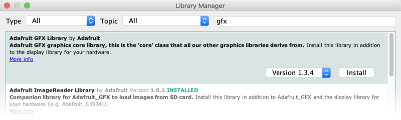
Three libraries need to be installed using the Arduino Library Manager…this is the preferred and modern way. From the Arduino “Sketch” menu, select “Include Library” then “Manage Libraries…”

Type “gfx” in the search field to quickly find the first library — Adafruit_GFX:
Repeat the search and install steps, looking for the Adafruit_ST7735 library. If using an older Arduino IDE (pre-1.8.10), also locate and install Adafruit_BusIO.
After restarting the Arduino software, you should see a new example folder called Adafruit_ST7735 and inside, an example called graphicstest.

In the graphicstest source code, you need to changes some code for this to work. Start by looking for the lines as follows:
  // Use this initializer if you're using a 1.8" TFT
  tft.initR(INITR_BLACKTAB);   // initialize a ST7735S chip, black tab

  // Use this initializer (uncomment) if you're using a 1.44" TFT
  //tft.initR(INITR_144GREENTAB);   // initialize a ST7735S chip, black tab
Comment out the line that initializes the Black Tab, and uncomment the second so it initializes with Green Tab, so it looks like:
  // Use this initializer if you're using a 1.8" TFT
  //tft.initR(INITR_BLACKTAB);   // initialize a ST7735S chip, black tab

  // Use this initializer (uncomment) if you're using a 1.44" TFT
  tft.initR(INITR_144GREENTAB);   // initialize a ST7735S chip, black tab
Now upload the sketch to your Arduino. You may need to press the Reset button to reset the arduino and TFT. You should see a collection of graphical tests draw out on the TFT.

Changing Pins
Now that you have it working, there's a few things you can do to change around the pins.
If you're using Hardware SPI, the CLOCK and MOSI pins are 'fixed' and cant be changed. But you can change to software SPI, which is a bit slower, and that lets you pick any pins you like. Find these lines:
// Option 1 (recommended): must use the hardware SPI pins
// (for UNO thats sclk = 13 and sid = 11) and pin 10 must be
// an output. This is much faster - also required if you want
// to use the microSD card (see the image drawing example)
Adafruit_ST7735 tft = Adafruit_ST7735(TFT_CS,  TFT_DC, TFT_RST);

// Option 2: use any pins but a little slower!
#define TFT_SCLK 13   // set these to be whatever pins you like!
#define TFT_MOSI 11   // set these to be whatever pins you like!
//Adafruit_ST7735 tft = Adafruit_ST7735(TFT_CS, TFT_DC, TFT_MOSI, TFT_SCLK, TFT_RST);
Comment out option 1, and uncomment option 2. Then you can change the TFT_ pins to whatever pins you'd like!
You can also save a pin by setting
#define TFT_RST 9
to
#define TFT_RST 0
and connecting the RST line to the Arduino Reset pin. That way the Arduino will auto-reset the TFT as well.


