In this project we're building a wearable HD monitor. This is great for anyone looking to make their own a personal display.

A 5' hdmi display, Arduino Micro and a 9-DOF motion sensor are housed inside a 3d printed enclosure.

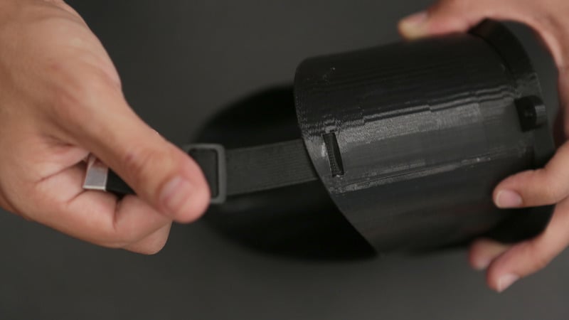
The outer hood is printed in PLA and Ninjaflex, fusing two different materials making a rigid frame with a flexible hood.

A mounting bracket secures the components to a faceplate with machine screws, making this a solid construction.

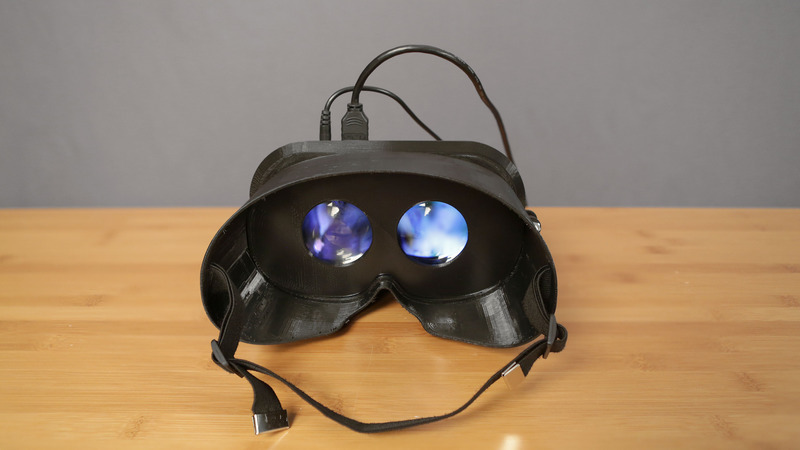
Make this into a DIY Oculus Rift by mounting a pair of aspheric lenses to the inner faceplate to split screen for stereoscopic video.

Prerequisite Guides

Before starting this project, we recommend doing a walk-through of the following guides to get you familiar with the hardware, and soldering (if your new to the craft!).

Parts

We have all the parts in the shop for building this project. The goggles can be 3D Printed or get some nice ones on the internets.

Tools & Supplies

The following tools and supplies will get you started on your build.

Adjust to fit your face

Edit any of the parameters to customize and adjust each part of the video goggle design. You can edit the size to fit your face and head shape.

Cable Port sides

Choose which side of the cables plug into the driver board by choosing which file to print.

Adjust the hood

Customize the hood shape by editing the outer faces of the cylinders that create the curves for the hood. You can edit the forehead, checks and nose sizes to fit your face.

3D Printed Goggle Enclosure

This 4 piece design houses the components and keeps them secured with machine screws. The Arduino Micro and 9 DOF are mounted to the back frame with 4 screws. 2 aspheric lenses are mounted inside the frame panel. The lens frame is secured in place by the two rails on each side, inside of the hood. The 5.6 Display is mounted to the back frame that is secured to the enclosure with another set of machine screws. A total of 16 screws makes this pretty solid and durable video goggles.

Slicer Settings

We recommend using the slice settings below. For really great quality prints, we recommend using PLA over ABS.

vr-tv-mnt.stl
vr-lensFrame.stl
vr-driver.stl

vr-hood.stl


PLA @ 230
90/120 mm travel / feed
.2 layer height

NinjaFlex @235
Z height change at 30mm


1.5 - 3 hours


7 hours


Multi-Material

The outer hood is printed in PLA and NinjaFlex, fusing two different materials making a rigid frame with a flexible hood.
You don't need dual heads, just set the Z layer height to stop at 30mm and switch the filament to NinjaFlex.

Mount Motion Sensor

Line up the 9-DOF Breakout board on the flat side of vr-tv-mnt.stl part. Use 4 #2-32 1/8' screws to secure the board on the the mount.

Cable management

Twist and curl the control board wire into a manageable shape that can fit over the middle of the driver board. It should hover right above the center.

Driver Tray

Use #2-56 x 3/8 screws to fasten the driver board on to the vr-driver.stl part. All seven holes can be used, but 4 screws on the outer most holes provides a solid "no-shake" hold.

Controller Mounts

Secure the controller board to the two tallest standoffs using two #4-40 x 1/8 screws.

Prep monitor screws

Attach the frame on to the monitor by adding four #2-56 x 3/8 screws to each outer most corner. The monitor stand offs are a bit shorter than the rest. Thread each half way and align the holes to the monitor tabs on each corner.

Assemble Mount

Guide each corner into place, and thread each screw in. Thread the screws one third of the way through the stand off and monitor tabs.

Cable management

Tuck away the wires that connect the monitor to the driver board. Hide the cables between the board and monitor. Careful not to bend or tug those tiny wires!

Attach driver board to monitor

Align the monitor assembly on to the vr-mtn.stl part. Remember you can choose which way the (HDMI + Power)wires will connect into the monitor, either from the top or from the bottom.
The #2-56 x 3/8 screws should thread down into the vr-mnt.stl but not all the way through the part. Insure the screws are tight and all of the components are jiggle free!

Attach monitor to goggles

Thread 2 #6-32 x 1' screws that will attach the vr-mtn.stl part with vr-hood.stl part.
Use #6 nuts to securely hold both parts together.

Assemble Lens frame

Insert each lens into the vr-lens.stl part. Both surfaces of the lens bulge outwards, so the lips are designed to hold the biconvex lens around the bulge.

Rubber gaskets

Reuse the rubber gasket that each lens comes with. The inner lining of the lens lips have a groove that will securely gips the lens on to the vr-lens.stl part.

Lens frame rails

Guide the lens frame assembly inside the top hood to assemble the goggles. The rails on the side will grip on to the lens frame assembly.

Attach head straps

The top part of the hood flaps have two holes to attach the elastic band. Thread the band through the bottom hole and then into the top hole to secure each side of the band.
Pull the band through until the band can fit around your head.

Power up

Plug in the 9v power adapter and an HDMI cable from a video source. You can watch 3d stereoscopic videos or movies or even immersive head-tracking enabled 3d games.
Add VR functions to your video goggles by reading the software setup guide from Ahmet YILDIRIM

You can download the files from:
https://github.com/ayildirim/OpenVR

You can even enable 3d head-tracking enabled games!

This guide was first published on Aug 07, 2014. It was last updated on Aug 07, 2014.