The examples in this guide are no longer supported. Please check out the Adafruit eInk Display Breakouts guide for CircuitPython and Python usage: https://learn.adafruit.com/adafruit-eink-display-breakouts

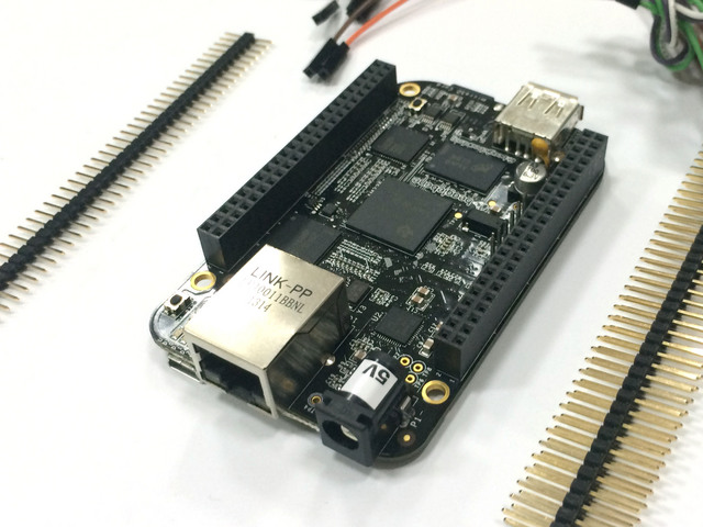
Insert the header segments
Insert the double-sided male header sections into the BeagleBone's headers. You can use both sides to create a nice stand for the display.


Connections:
Start by connecting Pin 1 of the breakout cable (red wire) to the header pin for 3.3v.Continue making connections in the order listed below. There are duplicate wire colors, so don't mix them up!
Make connections to:
- (Red #1) -> P9-03
- (Green #6) -> -?- P9-39 (not yet)
- (Yellow #7) -> P9-22
- (Orange #8) -> P9-27
- (Brown #9) -> P9-14
- (Black #10) -> P9-26
- (Red #11) -> P9-12
- (White #12) -> P9-23
- (Grey #13) -> P9-15
- (Purple #14) -> P9-21
- (Blue #15) -> P9-18
- (Orange #18) -> - Vcc P9-04
- (Brown #19) -> P9-17
- (Black #20) -> P9-01

Now you are done wiring and ready to test the display!