Introduction

This project isn't a kit (and won't ever be) so the instructions are more laissez-faire, with many opportunities for the maker to change elements or modify the design. Take it more as a guideline (and use common sense) than a rigorous step-by-step!

Parts list

To make this project you'll need:

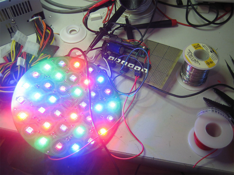
  • 36 or 37 1+ Watt LEDs. there are 2 Watt LEDs that are now easily available. For color versatility you can use 12 each of red green and blue. Or you can go with 18 each of green/blue for more effective dazzling. These range around $3 each. Look on eBay or other closeouts to get slightly-older LEDs for less. We used some older Cree XLamp XR-E 7090
  • You'll also need lenses/optics for each LED. Go with narrow-beam lenses, about 20mm diameter. 6 or 5 degree will be most effective. (Like this, but make sure you get ones that match your LED)
  • Balancing resistors, one for each LED. I used 1.0 ohm 1210's
  • For red LEDs (and maybe green/blue depending on your power supply) you may need a choke resistor 0.5 ohm at 5W may be OK. The internal resistance of the battery and Rds of the FET will make a difference, so do math and measurements!
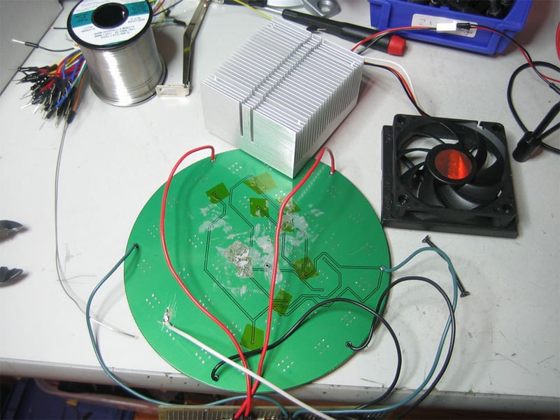
  • 6" diameter LED plate, see the downloads page for layout. This holes the LEDs and lenses. In theory a aluminum core LED is helpful but we found that for quick blasting, FR4 with copper fill worked just fine.
  • 16 or 18 gauge wire for connecting things up
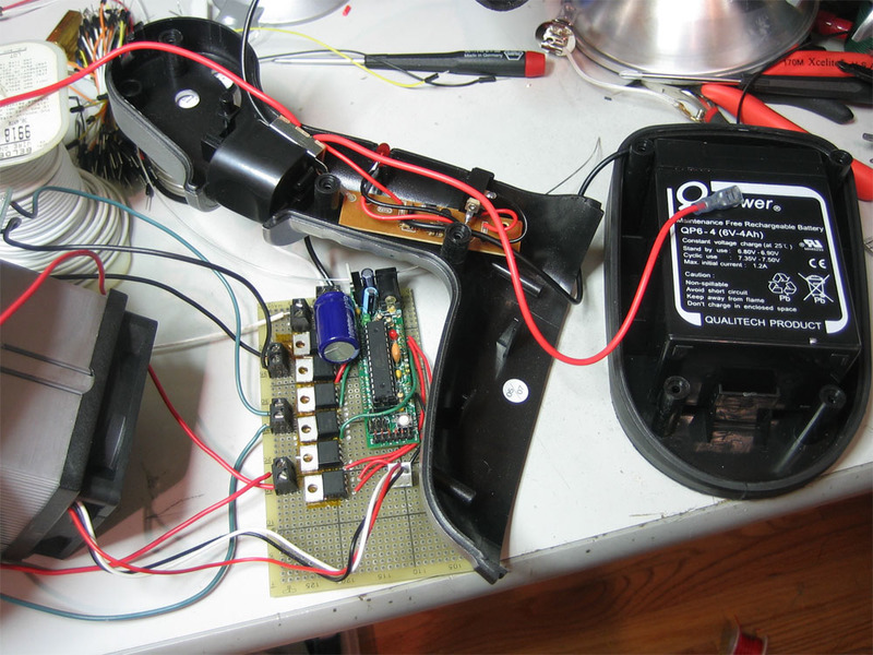
  • 6 N Channel logic level power MOSFETs. We used FDP6030BLs. Nearly anything that can sink 2A is just fine.
  • Arduino or other microcontroller. The AVR atmegax8 series such as found in the arduino is handy because it has 6 hardware PWMs. We used a DC boarduino and attached an FTDI cable to upload the firmware
  • Battery capable of sourcing 4A at 4V+. 3 D cells or a lead acid is a good choice. We used a 4A 6V SLA that came with the lantern
  • Heatsink. A spare AMD processor heatsink and fan worked nicely and was free!
  • 9V battery + holder with switch for the arduino, seperate supplies prevent noise issues when driving such large loads
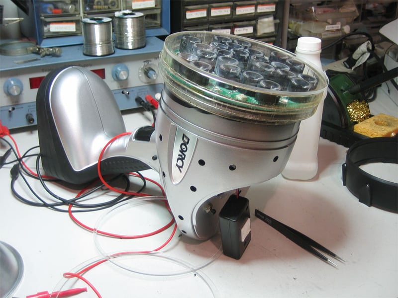
  • Enclosure. We repurposed a cheap yet enormous flashlight from Sears. It was pricey at $40 but had the benefit of including a lead acid battery (which would have run almost $20 with shipping) and a basic lead acid charger.
  • Power supply for testing, a ATX power supply is a good way to generate 5A+ at 5V

Make your own

You'll want to start by getting an LED plate fabbed at your favorite PCB manufacturer and acquiring all the materials necessary.

Start by soldering in one color of LEDs (in the photo there are a few LEDs soldered in from other strings. Go with green to start.
You'll want a nice powerful soldering iron, use leaded solder since its hard enough to solder to the copper plane!
Use 1 ohm (or so) 1210's for the balancing resistors.
For testing you'll want a benchtop supply, or use an ATX power supply with a jumper between the green power line and ground.
Test the LEDs to make sure you put them in the right place. Each 'string' is 6 LEDs.
Solder in all the green LEDs.
Once you have a single color in place, you'll want to build the controller. I used a boarduino (Arduino clone) but any microcontroller is fine. Wire up the power FETs so that the gates are connected to the hardware PWM outputs, and the sources to ground.
To make traces on perfboard high-current-capacity you can use a 20 gauge wire as a backing and solder on top to make a path.
Which you can sort of see here
You don't have to wire up all the FETs now, start with one. We used 5.08mm (0.2") terminal blocks to make wiring easy.
Do lots of testing and be careful to connect power up properly since there are no protection diodes.
You can load some PWM testing firmware onto the microcontroller to check the LEDs as you work.
Complete soldering in all the LEDs
A final test PWMing through all the LEDs. It heats up fast so keep the max power low and/or don't run it more than half a minute.
Since we were too cheap to get a proper metal PCB, we'll be attaching a heatsink to the outside. While far from ideal, a spare AMD processor heatsink worked just fine. Remove the fan, take off the metal clip and then reattach the fan. Check the fan to see if it will run off of 9V. Ours did OK.
If you have thermal paste, spread some on the heatink. If you didn't tent the vias, use kapton tappe or similar to prevent them from shorting to the heatsink.

Next up is the enclosure. We found the Dorcy 41-1088 lantern at Sears for about $40. It's very close to the right size so we went with it.

It looks like this.

Open up the bottom to reveal a 6V, 4A sealed lead acid battery. This battery works pretty well. There's enough internal resistance that when the LEDs are on, the voltage out drops to 4V which is rather convenient.

It comes with a charger but putting it on a 7V benchtop supply will charge it much faster (about 4 hours instead of 20).
Test the circuit with the heatsink and fan activated.
Then try it with the battery as the power supply.

Check the temperature of the LEDs, we didn't get above 58 degrees C which is pretty good.

Open up the rest of the lantern and remove the reflector and halogen bulb.
Reassemble the body.
Extend the power lines and wire them to the main control PCB.
The PCB is cut down and tucked into the slot behind where the reflector went.
The plate sits in front, sadly it's just slightly too small to go into the enclosure. However, this way there is more space for the heat sink.
Lenses are snapped onto the LEDs. I used superglue to tack them down. This is a major mistake so don't do what I did because then the fume damage the lenses and they need to be cleaned. There's probably a better glue to use. Perhaps epoxy?
A 9V battery is wired up to the arduino. All the lenses are put on.

We cut out a simple lens protector from acrylic on our laser cutter.

Showing the fit before we finish.
With some gaff or packing tape to attach the lens protector, we're done!

This guide was first published on Apr 12, 2013. It was last updated on Apr 12, 2013.

This page (Design) was last updated on Apr 10, 2013.

Text editor powered by tinymce.